
With the rise of electric vehicles, portable electronics, and renewable energy systems, the need for accurate and efficient battery simulation software has never been greater. Engineers and researchers require powerful tools to understand and predict the thermal, electrical, and electrochemical behavior of batteries under real-world conditions. ANSYS Fluent Battery Module has emerged as a robust and comprehensive solution to simulate battery performance, cooling, and degradation with high precision. This article explores batteries in depth — from their fundamental working principles to advanced simulation strategies — and presents ANSYS Fluent as one of the best battery simulation software platforms available today. By delving into the features of the ANSYS Fluent Battery Module, we aim to provide valuable insights for professionals seeking to enhance their understanding of battery systems.
What Is a Battery? A Quick Overview
A battery is an electrochemical device that stores and releases electrical energy through chemical reactions. It typically comprises (Fig.1):
- Anode (negative electrode)
- Cathode (positive electrode)
- Electrolyte (ion-conducting medium)
When a battery discharges, electrons flow from the anode to the cathode through an external circuit, powering devices, while ions move through the electrolyte to maintain charge balance.
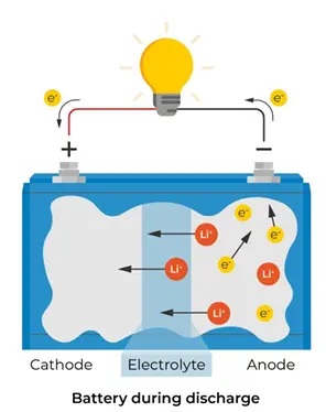
Figure 1- How does a battery work?
Types of Batteries and Their Applications
Generally, there are two basic types of batteries: Primary and Secondary. Table 1 shows the widely used battery types for both primary and secondary.
Table 1- Overall Battery Classification: Primary and Secondary
|
Battery Classification |
Battery Type | Chemical Compound |
Typical Use |
| Secondary Batteries | Lithium-Ion | LiCoO₂ (Lithium Cobalt) | Smartphones, laptops, electric vehicles |
| Lithium Polymer | LiCoO₂ (Lithium Cobalt) | Drones, RC vehicles, portable electronics | |
| Lithium Metal | Li (Lithium) | High-energy applications, military use | |
| Nickel-Metal Hydride | NiMH (Nickel/Manganese) | Hybrid vehicles, power tools, cameras | |
| Nickel-Cadmium | NiCd (Nickel/Cadmium) | Power tools, emergency lighting | |
| Lead Acid | Pb (Lead) | Cars, UPS, solar systems | |
| Primary batteries | Zinc-Carbon | Zn/MnO₂ (Zinc/Manganese) | Low-drain devices (e.g., clocks, remote controls) |
| Alkaline | Zn/MnO₂ (Zinc/Manganese) | Remote controls, flashlights, toys | |
| Lithium Iron Disulfide | Li-FeS₂ (Lithium Iron Disulfide) | High-drain applications (e.g., cameras, outdoor equipment) | |
| Lithium-Thionyl Chloride | LiSOCl₂ (Lithium Thionyl Chloride) | Medical devices, military, remote sensors | |
| Lithium Manganese Dioxide | LiMnO₂ (Lithium Manganese Dioxide) | Cameras, military, emergency devices |
Primary batteries, also referred to as disposable batteries, are non-rechargeable, meaning they can only be used once. In many applications, their initial charge tends to last much longer than that of rechargeable batteries. These batteries have a simple, lightweight design and do not contain any fluid, earning them the name “dry cells,” such as Zinc-Carbon cells.
On the other hand, secondary batteries are rechargeable and have a longer lifespan because they can be recharged multiple times. Their design is more complex, incorporating various materials for the anode, cathode, and electrolytes. Examples of secondary batteries include lead-acid, nickel-cadmium (NiCd), and lithium-ion batteries. Figure 3 illustrates the two main types of batteries: the primary cell battery, represented by a standard alkaline battery, and the secondary cell battery, exemplified by a rechargeable lead-acid battery.
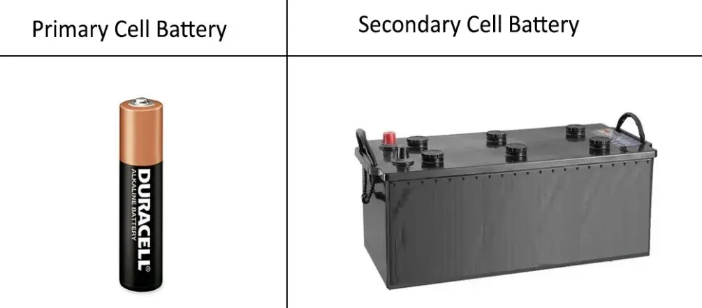
Figure 2- Example of Two Common Batteries: Primary and Secondary Cell
Charging and Discharging Process of a Battery
The figure 3 depicts the charging and discharging processes of a lithium-ion battery, divided into two sections:
- Charge Procedure: During the process of charging, the battery is connected to a charger, causing lithium ions (Li⁺) to move from the positive anode to the negative cathode. Electrons (e⁻) flow through the external circuit towards the anode, while current (I) flows in the opposite direction.
- Discharge Procedure: During the process of discharging, the battery is connected to a load (e.g., a light bulb), and the lithium ions move from the negative anode to the positive cathode. The flow of electrons (e⁻) reverses direction, providing electrical energy to the load, while current (I) flows from the positive to the negative terminal.
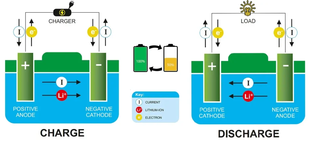
Figure 3- Charging and Discharging Process of a Lithium-Ion Battery
Why Battery Simulation Is Essential?
Battery behavior is nonlinear and influenced by multiple coupled physical phenomena, including:
- Heat generation during charge/discharge
- Electrochemical degradation
- Capacity fade
- Voltage drops due to internal resistance
This is where tools like best battery simulation software like ANSYS Fluent become crucial, although open source battery simulation software like OpenFOAM, a free battery simulation software, can be utilized. Simulating these parameters helps engineers design safer, more efficient, and longer-lasting battery systems.
ANSYS Fluent Battery Module
The ANSYS Fluent Battery Module is a specialized extension within ANSYS Fluent that allows users to simulate the thermal-electrochemical behavior of battery cells and packs. It combines CFD, thermal analysis, and electrochemical modeling into a single environment. With its robust features, it allows engineers and researchers to optimize battery design and performance through detailed simulations. This figure 4 shows a 3D model of a prismatic battery cell commonly used in ANSYS Fluent Battery Module simulations.
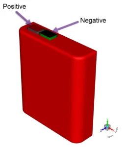
Figure 4- 3D View of a Battery Cell Showing Positive and Negative Terminals
How to Enable the ANSYS Fluent Battery Module in ANSYS Fluent
Figure 5 illustrates how to enable the Battery Module in ANSYS Fluent. To do this, follow these steps:
- Open ANSYS Fluent → Access the Console (where you can enter commands)
- Define Models: Type this command to access the models: /define/models/addon-module
- Select the Battery Model: You will see options for different battery models, such as: 7. Single-Potential Battery Model and 8. MSMD Battery Model
- Confirm Activation: After entering the module number, the battery module will be enabled for your fluent session. You can now proceed with your simulations involving battery modeling.
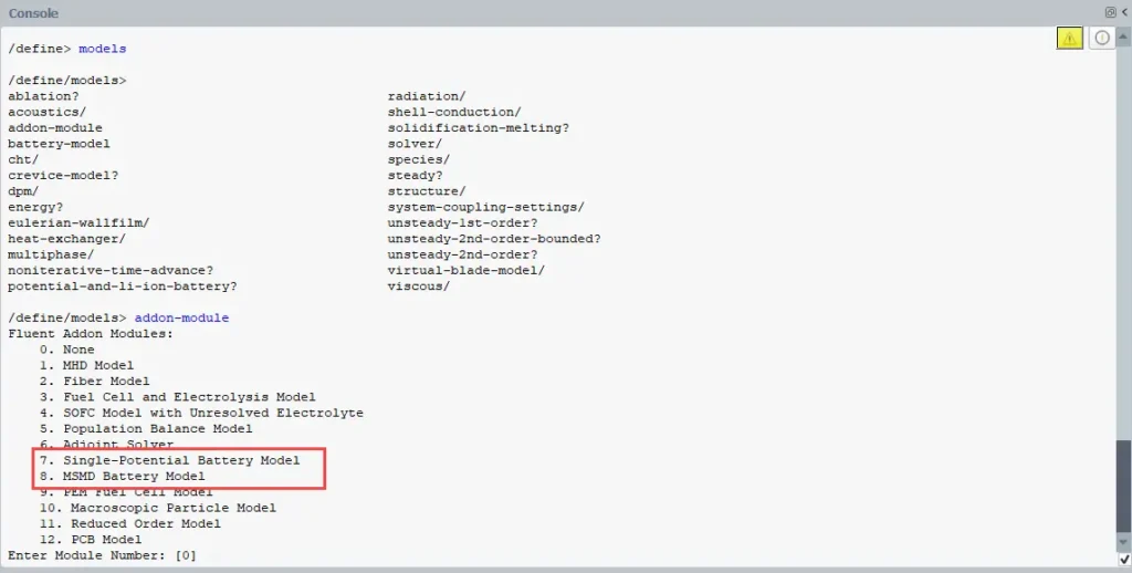
Figure 5- The process of activating the ANSYS Fluent Battery Module in the command line area of ANSYS Fluent
Description of the ANSYS Fluent Battery Model
Once the ANSYS Fluent battery simulation is activated (Fig.6), you will be able to model battery behavior in your simulations.
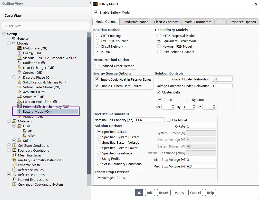
Figure 6- Schematic of Battery Model Panel in ANSYS Fluent
Model Options Tab
The Model Options Tab of the Battery module in ANSYS Fluent is a critical section that allows users to configure various aspects of battery modeling. Below are the detailed descriptions of each of the six sections available in this tab. (Fig.7)
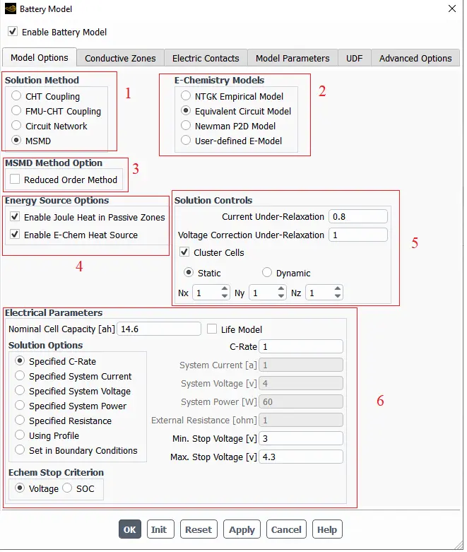
Figure 7- Schematic of Model Options Tab in Battery Model Settings
1.Solution Method Section
This section allows users to select the numerical method for solving the battery model. The options include:
- CHT Coupling: Coupled Heat Transfer, which solves for fluid flow and heat transfer simultaneously.
- FMU-CHT Coupling: A specific coupling method for modeling the interactions between fluid mechanics and heat transfer.
- Circuit Network: A method that models the battery as a network of electrical components, allowing for a more circuit-like analysis.
- MSMD: Multi-Scale Multi-Domain method, which is designed for complex battery simulations that require detailed resolution at different scales.
2. E-Chemistry Models Section
This section allows users to select the electrochemical model that will govern the battery’s performance. Options include:
- NTGK Empirical Model: A simplified empirical model for estimating battery behavior.
- Equivalent Circuit Model: Represents the battery as an electrical circuit, useful for analyzing dynamic responses.
- Newman P2D Model: A more detailed model that considers both the electrochemical reactions and transport phenomena in the battery.
- User-defined E-Model: Allows for a custom electrochemical model to be defined by the user for specific battery characteristics.
3. MSMD Method Option Section
This section provides additional settings for the MSMD approach. Reduced Order Method Enables a simplified version of the MSMD method, which can reduce computational time while maintaining reasonable accuracy in results.
4. Energy Source Options Section
This section allows users to enable specific energy sources in the simulation:
- Enable Joule Heat in Passive Zones: Activating this option allows for the calculation of Joule heating effects in zones not directly involved in electrochemical reactions.
- Enable E-Chem Heat Source: This option enables the consideration of heat generated from electrochemical reactions, which is critical for accurate thermal modeling of the battery.
5. Solution Controls Section
This section includes parameters that control the solution process:
- Current Under-Relaxation: A factor that helps stabilize the iterative solution process by controlling the rate at which the current solution is updated (default is 0.8).
- Voltage Correction Under-Relaxation: Similar to current under-relaxation, this controls how quickly the voltage solution converges (default is 1).
- Cluster Cells: This option allows the user to choose how cells are clustered during the simulation, with options for static or dynamic clustering.
- Static: Fixed cell clustering throughout the simulation.
- Dynamic: Allows for changes in clustering based on simulation conditions.
- Nx, Ny, Nz: These parameters define the number of clusters in the x, y, and z directions.
6. Electrical Parameters
This section provides the settings for the electrical characteristics of the battery:
Nominal Cell Capacity [ah]: Specifies the capacity of the battery cell in ampere-hours (default is 14.6).
Life Model: Selects the model for estimating the battery’s lifespan.
C-Rate: Defines the rate at which the battery is charged or discharged.
Solution Options: Users can specify various electrical parameters including:
-
- Specified C-Rate: Define the charge/discharge rate.
- Specified System Current: Set a specific current for the system.
- Specified System Voltage: Set a specific voltage for the system.
- Specified System Power: Set a specific power level.
- Specified Resistance: Set a resistance value for the system.
- Using Profile: Allows users to apply a predefined profile for charging/discharging.
- Set in Boundary Conditions: Option to set these parameters directly in the boundary conditions.
Echem Stop Criterion: This defines the criteria for stopping the electrochemical simulation based on:
-
- Voltage: A specific voltage threshold.
- SOC: State of Charge, which can also be used to determine when to stop the simulation.
Conductive Zones Tab
In the Battery module’s Conductive Zones section (Fig.8), users can define two types of components:
- Active Components
This section lists components that are designated as active in the battery model. Active components typically contribute to the battery’s charge and discharge processes. These components are essential for current generation and consumption. Users can filter the list of active components using the filter text box.
- Passive Components
This section lists components that are considered passive, meaning they do not actively contribute to the battery’s electrical behavior but may affect overall performance. Necessary for mechanical support and ionic transport.
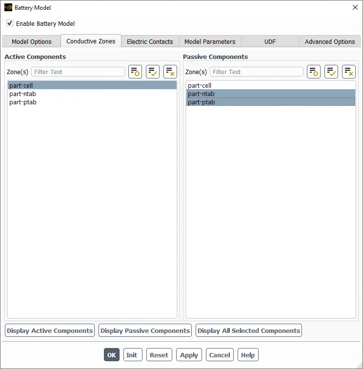
Figure 8- Schematic of Conductive Zones Tab in Battery Model Settings
Electric Contacts Tab
The Electric Contacts Tab in the Battery module of ANSYS Fluent is designed to define and manage the electrical connections within a battery model. (Fig.9).
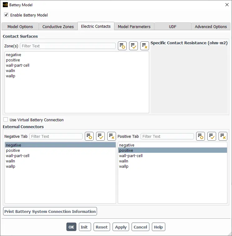
Figure 9- Schematic of Electric Contacts Tab in Battery Model Settings
1.Contact Surfaces
- Zone(s) Field: This section lists various zones in the battery model that are relevant for electric contact. The zones include:
- negative: Represents the negative electrode surface.
- positive: Represents the positive electrode surface.
- wall-part-cell: Refers to the interface between the wall and the battery cell.
- wallnand wallp: Likely indicate different wall components or partitions in the battery structure.
- Specific Contact Resistance: This field allows users to input the specific contact resistance values (measured in ohm-m²) for the defined zones, which is crucial for accurately modeling the electrical performance of the battery.
- Use Virtual Battery Connection: A checkbox to enable or disable the use of a virtual battery connection, allowing for flexible simulation setups.
2.External Connectors
- Negative Tab and Positive Tab: Users can define external connectors for both the negative and positive terminals of the battery. Each tab includes fields for specifying relevant parameters or properties associated with these connections.
- Print Battery System Connection Information: A button to generate and print information about the battery system’s connections, aiding in documentation and analysis.
Model Parameters Tab
The Model Parameters Tab in the Battery Model interface is crucial for defining the polarization characteristics and other parameters that govern the battery’s performance (Fig.10).
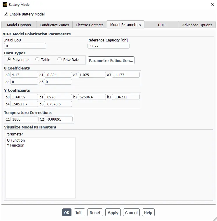
Figure 10- Schematic of Model Parameters Tab in Battery Model Settings
1.NTGK Model Polarization Parameters
- Initial DoD (Depth of Discharge): This field allows users to set the initial state of charge for the battery, indicated as a percentage (in this case, 0%).
- Reference Capacity [ah]: This specifies the reference capacity of the battery, which is set to 32.77 Ah, serving as a baseline for calculations.
2.Data Types
Users can select the type of data to represent the polarization characteristics. There is also a Parameter Estimation… button that opens a feature for estimating parameters based on input data.
- Polynomial: A polynomial function representation.
- Table: A tabular format for data input.
- Raw Data: For direct data input.
3.U and Y Coefficients
This section contains coefficients that are part of the U or Y function, which describes the voltage behavior ((such as current or resistance) of the battery under different conditions.
4.Temperature Corrections
This section includes two constants (C1 and C2) used to adjust model parameters based on temperature.
5.Visualize Model Parameters
This area allows users to visualize the U and Y functions based on the defined coefficients. Users can see the parameter values for both functions in a designated area, which helps in understanding the model’s behavior.
UDF Tab
User-Defined Functions (UDF) Section allows users to specify custom functions that can enhance or modify the battery model’s behavior beyond the standard options provided by the software (Fig.11).
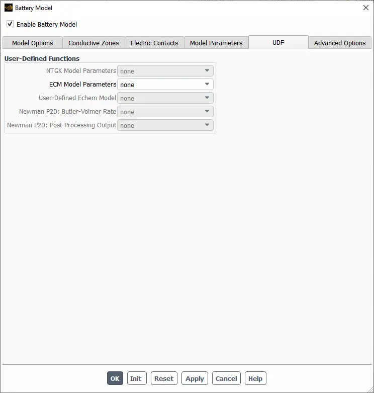
Figure 11- Schematic of UDF Tab in Battery Model Settings
- NTGK Model Parameters: This dropdown allows users to select an NTGK (Nernst-Planck-Taylor-Gibbs-Kasama) model, if applicable. If no model is selected, it shows “none.”
- ECM Model Parameters: Similar to the NTGK section, this dropdown allows users to choose an equivalent circuit model (ECM) for the battery. The option defaults to “none” unless a specific model is selected.
- User-Defined Echem Model: This field enables the selection of a custom electrochemical model that the user may have defined, providing flexibility in modeling the electrochemical processes within the battery.
- Newman P2D: Butler-Volmer Rate: This dropdown allows users to specify a custom Butler-Volmer rate equation if they have implemented a user-defined function for this purpose.
- Newman P2D: Post-Processing Output: This option lets users select custom post-processing outputs related to the Newman P2D model, enhancing the analysis capabilities of the simulation results.
Advanced Options
The Advanced Options Tab in the Battery module of ANSYS Fluent provides specialized settings for managing detailed aspects of the battery model (Fig.12).
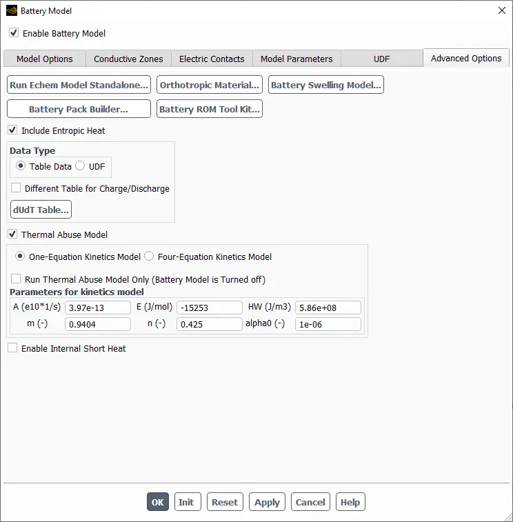
Figure 12- Schematic of Advanced Options Tab in Battery Model Settings
1.Include Entropic Heat
This checkbox allows users to include the effects of entropic heat in the battery model, which can be important for accurately modeling thermal behavior during charge and discharge cycles.
2.Data Type Section
Users can choose how to input data:
-
- Table Data: This option allows users to input data in tabular format.
- UDF: Allows for custom User-Defined Functions to be utilized for inputting data.
3.Different Table for Charge/Discharge
Provides the capability to use separate tables for charge and discharge processes.
dUdT Table: A button to access or define a table specifically for the change in voltage with temperature (dUdT).
4.Thermal Abuse Model Section
Users can choose between:
- One-Equation Kinetics Model: A simplified approach for modeling reaction kinetics.
- Four-Equation Kinetics Model: A more complex model that provides a detailed representation of the kinetics involved.
- Run Thermal Abuse Model Only: An option to run the thermal abuse model independently of the battery model being turned off.
5.Parameters for Kinetics Model
Various parameters related to the kinetics model are provided, including:
-
- A (e10^1/s): A coefficient for the reaction rate.
- E (J/mol): Activation energy.
- HW (J/m³): Heat of reaction.
- m (-): A parameter related to the reaction kinetics.
- n (-): Another parameter that affects the kinetics.
- alpha0 (-): A coefficient used in the model.
6.Enable Internal Short Heat
A checkbox to enable modeling of internal short heat effects, which can significantly impact battery performance and safety.
ANSYS Fluent Potential / Electrochemistry Module
The ANSYS Fluent Potential / Electrochemistry Module interface is designed for setting up and configuring electrochemical simulations, specifically for lithium-ion batteries (Fig.13).
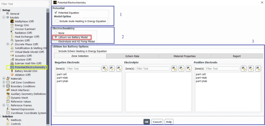
Figure 13- Schematic of ANSYS lithium ion battery module
Potential Section
This area allows users to configure the potential equation settings for the electrochemistry module.
Model Option: A checkbox labeled “Include Joule Heating in Energy Equation” is available, allowing users to account for Joule heating effects in the energy balance of the simulation.
- Electrochemistry Section
The user has the option to choose between different electrochemistry models:
- None: Indicates no electrochemistry model is selected.
- Lithium-ion Battery Model: This option is selected, indicating that the simulation will focus on the behavior of lithium-ion batteries.
- Electrolysis and H2 Pump Model: This option is available but not selected, suggesting that the user can model electrolysis processes and hydrogen pumping if needed.
- Lithium-ion Battery Options: Zone Selection
Include Echem Heating in Energy Equation: A checkbox that allows the user to include electrochemical heating effects in the energy equation.
- Negative and Positive Electrode Section
These fields allow users to input the zones associated with the negative/ Positive electrodes of the battery. The options available for selection include: part-cell, part-ntab, part-ptab.
- Electrolyte Section
The interface provides a dedicated section for selecting the electrolyte zone(s). This is crucial as the electrolyte plays a vital role in facilitating ion transport between the electrodes during the electrochemical reactions that occur in the battery.
Potential / Electrochemistry Module: Echem Rate, Material Properties and Report Tabs
There are three tabs which are related to the Potential / Electrochemistry Module. In the following we will review them (Fig.14).
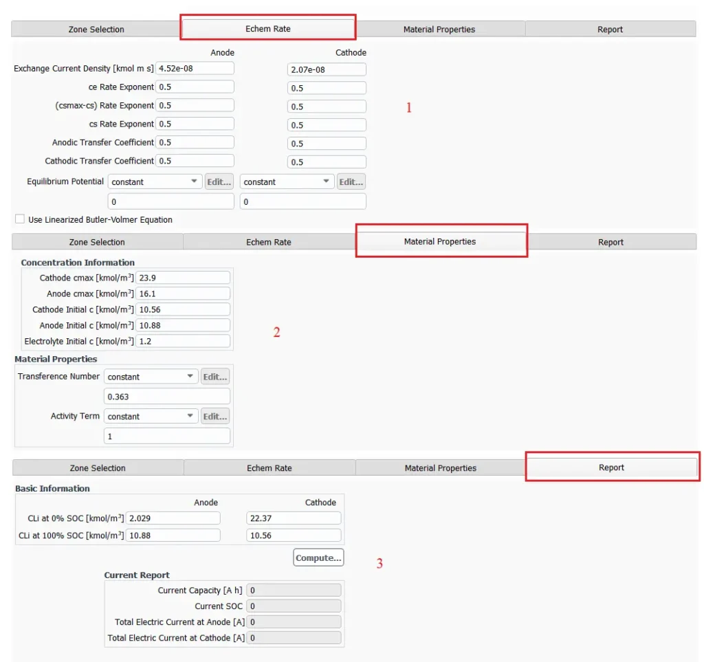
Figure 14- Potential / Electrochemistry Module: Echem Rate (1), Material Properties (2) and Report (3) Tabs
Echem Rate
This section focuses on defining the electrochemical reaction rates at both the anode and cathode, which are critical for simulating the electrochemical processes in the battery.
- Exchange Current Density [kmol m s]: These values represent the current density at which the electrochemical reactions occur at each electrode.
- Rate Exponents: These exponents indicate the reaction order for various electrochemical processes and can affect the kinetics of the reactions.
- Anodic and Cathodic Transfer Coefficients: Indicating a symmetrical charge transfer process at the electrodes.
- Equilibrium Potential: A field to define the equilibrium potential for both electrodes, with options to set it as constant or to edit further. It can be adjusted based on the specific conditions of the simulation.
- Use Linearized Butler-Volmer Equation: A checkbox allowing the user to apply a linearized version of the Butler-Volmer equation for simplifying the modeling of charge transfer kinetics.
Material Properties
- Concentration Information
This subsection provides fields for inputting concentration-related data for both the cathode and anode components of the battery:
- Cathode cmax [kmol/m³]: This represents the maximum concentration of species in the cathode material, indicating the upper limit for ion concentration during operation.
- Anode cmax [kmol/m³]: This indicates the maximum concentration of species in the anode material.
- Cathode Initial c [kmol/m³]: This field shows the initial concentration of ions or species in the cathode at the start of the simulation.
- Anode Initial c [kmol/m³]: This indicates the initial concentration of ions or species in the anode.
- Electrolyte Initial c [kmol/m³]: This field represents the initial concentration of the electrolyte, which is critical for facilitating ion transport between the anode and cathode.
- Material Properties: Transference Number: This value indicates the fraction of current carried by the ions in the electrolyte, which affects the efficiency of ion transport during battery operation.
- Activity Term: This constant value typically represents the activity coefficient for the species in the electrolyte, affecting how concentration influences electrochemical potential.
Report
Basic Information Section: This section provides critical information about the lithium-ion battery’s electrochemical state at different points of charge.
- CLI at 0% SOC [kmol/m³]: This parameter represents the lithium ion concentration at the anode and cathode when the battery is fully discharged (0% state of charge).
- CLI at 100% SOC [kmol/m³]: This indicates battery report full charge capacity, where the lithium ion concentration at both electrodes when the battery is fully charged (100% state of charge).
Current Report Section: This section summarizes the operational metrics of the battery based on the simulation results.
- Current Capacity [A h]: Displays the total capacity of the battery in ampere-hours.
- Current SOC: Shows the current state of charge of the battery.
- Total Electric Current at Anode [A]: Indicates the total current flowing through the anode.
- Total Electric Current at Cathode [A]: Indicates the total current flowing through the cathode.
Conclusion
The ANSYS Fluent Battery Module is a powerful and comprehensive tool for simulating the thermal, electrical, and electrochemical behavior of modern batteries, especially lithium-ion systems. It offers a range of modeling approaches—from empirical NTGK models to advanced physics-based methods like Newman P2D—enabling users to simulate charge/discharge cycles, heat generation, degradation, and performance with high accuracy. Whether you’re following an ANSYS Fluent battery module tutorial or building a custom simulation through UDFs, the platform offers unique flexibility and precision. Thanks to its advanced capabilities, ANSYS Fluent battery simulation has become a preferred choice for engineers and researchers working on ANSYS lithium ion battery projects, supported by a wide range of ANSYS battery simulation tutorial resources for beginners and experts alike.
FAQs
What is the ANSYS Fluent Battery Module?
The ANSYS Fluent Battery Module is a specialized extension within ANSYS Fluent that allows users to simulate the thermal, electrochemical, and electrical behavior of battery cells and packs, integrating computational fluid dynamics (CFD) and thermal analysis.
What types of batteries can be simulated using this module?
The module supports various types of batteries, including lithium-ion, nickel-metal hydride (NiMH), and lead-acid batteries, among others.
How do I enable the Battery Module in ANSYS Fluent?
To enable the Battery Module, open ANSYS Fluent, access the console, type the command to define models, select the battery model, and confirm activation.
What are the key components of a battery?
A battery typically consists of an anode (negative electrode), a cathode (positive electrode), and an electrolyte (ion-conducting medium).
Can users define custom electrochemical models?
Yes, users can specify User Defined Functions (UDF) to customize the electrochemical model beyond the standard options provided by the software.
Can I simulate lithium-ion batteries in ANSYS Fluent?
Yes, using the ANSYS lithium ion battery model, which includes thermal effects, charge/discharge cycles, and degradation.
What types of battery models are supported?
Fluent supports NTGK (empirical), Equivalent Circuit, Newman P2D (physics-based), and user-defined models.