


Turbomachinery represents one of the most essential practical applications of fluid mechanics in engineering. These rotating machines either impart energy to a fluid, as in pumps, or extract energy from it, as in turbines. The term “turbomachinery” itself is derived from the Latin root “turbo,” meaning a spinning or rotating object, and broadly refers to devices that involve energy transfer through fluid flow and a rotating shaft. In essence, any machine that interacts with a continuously flowing fluid—either to add energy or to harness it—using rotational motion can be categorized as turbomachinery. These systems are fundamental in various industries, including power generation, aerospace, and fluid transport, where efficient energy conversion between mechanical and fluid systems is critical.

Figure 1- The jet engines on modern commercial airplanes are highly complex turbomachines that include both pump (compressor) and turbine sections
Turbomachinery Classification
Turbomachinery can be classified into several categories based on different physical and functional characteristics. These classifications help engineers choose the appropriate machine type for a given application (Fig.2).

Figure 2- Turbomachinery: Types of classification
Flow Direction: Axial, Radial, and Mixed Flow
- Axial Flow: In axial-flow machines, the fluid flows parallel to the axis of rotation. These machines are compact and can handle large volumes at relatively low pressure differences. Common examples include axial compressors and axial turbines (e.g., in jet engines).
- Radial Flow (Centrifugal): In radial-flow machines, the fluid moves perpendicular to the shaft, typically from the center outward (as in centrifugal pumps or radial turbines). These are suitable for applications requiring higher pressure increases in a single stage.
- Mixed Flow: Mixed-flow machines combine axial and radial components, offering a balance between flow capacity and pressure rise. An example is a mixed-flow pump or some turbocharger compressors.

Figure 3- The impeller (rotating portion) of the three main categories of dynamic pumps: (a) axial flow, (b) centrifugal flow, and (c) mixed flow,
Energy Transfer: Power-Absorbing vs. Power-Generating
- Power-Absorbing Machines (Pumps, Fans, and Compressors): These machines add energy to the fluid by increasing its pressure or velocity. Mechanical power is supplied to the machine (usually via a rotating shaft), which is then transferred to the fluid.
- Power-Generating Machines (Turbines): These machines extract energy from the fluid and convert it into mechanical work. The fluid’s pressure or kinetic energy is reduced, and the rotating shaft delivers power to an external load.

Figure 4- (a) A pump supplies energy to a fluid, while (b) a turbine extracts energy from a fluid.
Fluid Type: Gas, Liquid, or Multiphase
-
- Gas Turbomachines: Used in systems like jet engines, gas turbines, or compressors where the working fluid is a gas.
- Liquid Turbomachines: Examples include water turbines and pumps that handle liquids such as water or oil.
- Multiphase Turbomachines: These are designed to handle a mixture of phases (e.g., gas-liquid or liquid-solid), such as in cavitating pumps, slurry pumps, or some chemical processing applications.

Figure 5- a) Gas turbines vs. b) Pumps
Flow Enclosure: Open-Flow vs. Enclosed-Flow
- Open-Flow Turbomachines (e.g., Propellers, Wind Turbines): In these machines, the fluid flows freely around the blades without any casing. They typically operate in open environments like air or water.
- Enclosed-Flow Turbomachines (e.g., Pumps, Gas Turbines): Here, the fluid flows through a casing or housing that guides and contains the flow. This setup is common in industrial machines requiring controlled flow and pressure conditions.

Figure 6- The propellers of a C-130J Super Hercules military transport aircraft
Main Components of Turbomachinery
Turbomachinery consists of several key components that work together to enable efficient energy transfer between a fluid and a rotating shaft.

Figure 7- Key components of turbomachinery
Rotor (Impeller / Runner / Blades)
- The rotating part of the machine that interacts directly with the fluid.
- In pumps and compressors, the rotor imparts energy to the fluid.
- In turbines, the rotor extracts energy from the fluid.
- Common forms: Impeller (pumps), Rotor blades (turbines), Propeller (open flow)
Stator (Guide Vanes / Nozzles / Diffusers)
The stationary part that directs the flow into or out of the rotor.
- Helps control the velocity and pressure of the fluid.
- Improves efficiency and reduces turbulence.
- In turbines: often designed as nozzles to accelerate fluid before it hits the rotor.
- In compressors/pumps: used as diffusers to decelerate the flow and increase pressure.
Shaft
- A mechanical component that transmits torque between the rotor and the driving or driven machine (e.g., motor or generator).
- Typically supported by bearings to ensure smooth rotation.
Casing (Housing)
- Encloses the internal components and contains the working fluid.
- In enclosed turbomachinery, the casing ensures pressure containment and directs the flow path.
- Also protects components and helps with heat dissipation or structural support.
Bearings and Seals
- Bearings support the rotating shaft and reduce friction.
- Seals prevent leakage of the working fluid and protect against contamination.
Inlet and Outlet (Suction and Discharge Sections)
- These are the flow entry and exit points of the machine.
- Designed to minimize losses and ensure smooth transition of the fluid.
Diffuser / Volute (in Pumps and Compressors)
- A diffuser slows down the flow to increase pressure.
- A volute is a spiral-shaped casing that collects fluid from the impeller and converts velocity into pressure.
Key Advantages of Turbomachines
The advantages of using turbomachines can be categorized as follows:
- High power transmission in a compact size and low weight, especially when compared to other types of machines such as reciprocating engines.
- High efficiency, making them ideal for continuous and large-scale energy transfer.
- No need to convert reciprocating motion into rotary motion, as turbomachines naturally operate with rotating elements.
- Cost-effective design, providing a high power-to-cost ratio relative to the useful output.
- Continuous energy exchange between the machine and the fluid, allowing for stable and steady operation.
Turbomachines Settings in ANSYS Fluent
Turbomachinery settings in ANSYS Fluent involve activating specialized tools for rotating domains, selecting appropriate flow models, and enabling advanced features like Rocky-DEM coupling for particle interaction. These settings support accurate simulation of complex fluid behavior in rotating equipment such as pumps, compressors, and turbines.
Turbomachinery Options in ANSYS Fluent
Fig.8 highlights the Turbomachinery menu options in the ANSYS Fluent interface. These options are specifically designed to facilitate the simulation, analysis, and post-processing of turbomachinery components (e.g., compressors, turbines, fans). Here’s a brief explanation of the options shown:
- Turbo Models: Allows enabling specific models tailored for turbomachinery simulations, such as rotating reference frames or blade passage models.
- Turbo Workflow: Provides a guided workflow for setting up turbomachinery simulations, ensuring that all necessary steps are completed systematically.
- Turbo Create: Assists in generating the geometry and computational grid for turbomachinery components (e.g., blades, passages).
- Turbo Topology: Helps define the topology of the turbomachinery geometry, such as blade rows, hub, shroud, etc.
- Spectral Content: Used to analyze frequency-domain data, which is particularly useful for assessing unsteady phenomena, such as blade passing frequencies or vibrations.
- Periodic Instancing: Enables defining and managing periodic boundaries, which are common in turbomachinery simulations to reduce computational effort by modeling only a portion of the geometry.
These tools streamline the process of performing detailed simulations of turbomachinery systems and are tailored to handle the complexities of rotating machinery.

Figure 8- Turbomachinery options in ANSYS Fluent
Mesh Motion Setting in ANSYS Fluent
Fig.9 shows a window in ANSYS Fluent configures Mesh Motion for a rotating fluid zone, commonly used in turbomachinery simulations such as pumps, turbines, or mixers. Enabling Mesh Motion allows the mesh itself to rotate over time, which is essential for capturing transient behavior in rotating systems. Here, for instance, the user sets the rotation-axis origin and direction (here, along the Z-axis), and defines the rotational speed as 500 rpm. This setup ensures that the zone physically rotates around a specified axis during the simulation, allowing for detailed analysis of unsteady flow patterns.
Unlike Frame Motion, which simulates rotation in a stationary mesh using a rotating reference frame (typically for steady-state cases), Mesh Motion is suited for transient simulations involving actual movement of the geometry. Translational velocity is left at zero, indicating that there’s no linear motion—only rotation. This approach is particularly useful when simulating blade-passing effects, rotor-stator interactions, or time-dependent flow features in rotating machinery.

Figure 9-Mesh motion settings for rotating zone in ANSYS Fluent
3D Fan Zone Panel in ANSYS Fluent
Fig.10 depicts the panel in ANSYS Fluent for a 3D Fan Zone, a simplified model used to represent the aerodynamic effect of rotating fans without resolving the actual blade geometry. This model adds momentum sources to the flow field based on empirical fan performance data, allowing simulation of axial, radial, and tangential flow effects. Parameters such as hub radius, tip radius, thickness, and inflection point define the fan’s geometry, while the fan origin sets the spatial location.
Here, as an example, the model includes an Axial Source Term, which is activated to simulate the fan’s effect on the axial direction of the flow. A fan curve method is used to provide performance data, and options for curve fitting and testing conditions such as angular velocity and temperature are included. This setup is ideal for HVAC systems, electronics cooling, or ventilation modeling, where simulating detailed fan blades is unnecessary and would be computationally expensive.

Figure 10- 3D fan zone configuration in ANSYS Fluent for simplified rotating fan modeling
Turbomachinery Simulations: Boundary Conditions
Fig.11 illustrates the configuration of boundary conditions for turbomachinery simulations in ANSYS Fluent, specifically focusing on the setup of a fan boundary condition. The left panel displays the list of boundary zones in the computational domain, categorized under internal and wall boundaries. The selected zone, “interior-fan,” is assigned as a fan boundary, which allows for the definition of a pressure jump across the fan based on the flow conditions. The configuration options for the fan boundary are shown on the right, where users can specify the pressure jump characteristics as a function of velocity, direction, and other parameters.
The right panel provides detailed inputs for defining the pressure jump. A polynomial profile is used to relate the pressure jump to the velocity magnitude, with coefficients defining the curve. The graph at the bottom shows the resulting pressure jump curve, providing a visual representation of the specified relationship. Additional options, such as reversing the fan direction or limiting the velocity range, allow for customization of the fan’s operating behavior. This setup is critical in accurately modeling the effects of turbomachinery components like fans, blowers, or compressors in fluid flow simulations.

Figure 11- Boundary conditions sets for turbomachinery simulations in ANSYS Fluent
Kinds of Turbomachines
Turbomachines are classified based on the type of fluid, direction of energy transfer, and application. The most common types include:
Wind Turbine
Converts wind energy into mechanical and subsequently electrical energy. Wind turbines are a vital source of renewable energy and are widely used in wind farms.

Figure 12- Wind Turbine: Open-Flow Turbomachines
Gas Turbine
Extracts energy from high-temperature gas flows and operates based on the Brayton cycle. Gas turbines are commonly used in thermal power plants, jet engines, and industrial applications.

Figure 13- Gas Turbine: Enclosed-Flow Turbomachines
Steam Turbine
Designed to extract energy from steam. These turbines are a core component of power plants that use the Rankine cycle. Since the presence of liquid water can damage the blades, the working fluid must remain in the vapor phase during expansion.

Figure 14- Steam Turbine: Enclosed-Flow Turbomachines
Hydraulic Turbines
Extract energy from liquid flows, most often water. They are found in hydropower plants and come in various forms, including Pelton, Francis, and Kaplan turbines, each suited to specific flow and head conditions.

Figure 15- Hydraulic Turbines: Enclosed-Flow Turbomachines
Compressors
Used to increase the pressure and velocity of gas-phase fluids. Common types include axial and centrifugal compressors, found in applications such as gas turbines, jet engines, and industrial refrigeration.

Figure 16- Compressors: Enclosed-Flow Turbomachine
Pumps
Designed to increase the pressure and move liquids. Pumps are extremely diverse, including centrifugal, axial, and positive displacement types, and are used across industries such as water treatment, oil and gas, and chemical processing.

Figure 17- Pumps: Enclosed-Flow Turbomachine
Fans
These machines generate airflow and fluid displacement in the gas phase. Fans operate at low pressure and are commonly used in HVAC systems, ventilation, and cooling applications.

Figure 18- Fans: Open-Flow Turbomachine
Turbomachines Applications
Turbomachines are fundamental components in systems where energy is transferred between a continuously flowing fluid and a rotating mechanical element. Due to their efficiency and versatility, they are extensively used across a wide range of industries.
Power Generation
Turbomachines are at the core of most energy generation technologies:
- Steam turbines are used in thermal power plants that operate based on the Rankine cycle to extract energy from high-pressure steam.
- Gas turbines, operating under the Brayton cycle, are essential in combined-cycle power plants and jet engines.
- Hydraulic turbines (e.g., Francis, Pelton, Kaplan) convert potential energy of water into mechanical energy in hydropower plants.
- Wind turbines harness the kinetic energy of wind to produce clean, renewable electricity.

Figure 19- An overview of the structure of wind turbine generators
Aerospace and Aviation
Turbomachines play a vital role in aerospace propulsion and onboard systems:
- Jet engines rely on axial compressors and turbines to compress air, generate combustion, and produce thrust.
- Helicopter rotors, acting as open-flow turbomachines, generate lift and propulsion.
- Turbopumps are used in rocket engines to feed fuel and oxidizers into combustion chambers.
- Turbomachinery CFD simulations are commonly employed for aerodynamic design, thermal analysis, and performance prediction in aerospace applications.
HVAC Systems (Heating, Ventilation, and Air Conditioning)
In HVAC, turbomachines enable fluid transport, pressure regulation, and thermal management:
- Centrifugal and axial fans circulate air through ducts and living spaces.
- Compressors pressurize refrigerants in cooling and heat pump cycles.
- CFD modeling of turbomachinery is widely used to optimize energy efficiency and airflow in HVAC system design.

Figure 21- Example of commercial HVAC system
Automotive Industry
Modern vehicles use turbomachines to boost performance and maintain thermal stability:
- Turbochargers and superchargers compress intake air to improve combustion efficiency.
- Pumps and fans regulate coolant and oil circulation, enhancing engine cooling and lubrication.
- Fuel transfer systems also incorporate small-scale pumps and turbomachinery elements.

Figure 22- Turbocharger vs Supercharger
Industrial and Manufacturing Applications
Turbomachines are critical to large-scale industrial processes:
- Pumps transport liquids in water treatment, oil refineries, and chemical plants.
- Compressors manage gas flow in natural gas pipelines, refrigeration, and industrial gas systems.
- Blowers and fans ensure adequate ventilation, particulate transport, and combustion support in furnaces and kilns.

Figure 23- Common types of blowers and fans
Domestic Applications
Turbomachines are found in many household systems:
- Centrifugal pumps in domestic water supply, heating systems, and washing machines.
- Fans in air conditioning units, vacuum cleaners, and ventilation devices.

Figure 24- TROTEC Garden Pump
Marine and Offshore Engineering
Turbomachines are widely used in marine propulsion and offshore processes:
- Propellers, a type of open turbomachine, provide thrust for ships and submarines.
- Pumps and hydraulic turbines support offshore energy systems and desalination plants.
- CFD analysis helps in designing marine turbomachinery for optimal hydrodynamic performance.

Figure 25- Ship propellers
Construction and Civil Engineering
In construction, specialized turbomachines are used for high-pressure applications:
- Cylindrical concrete pumps transport viscous slurries over long distances and heights.
- Due to experimental limitations, turbomachinery CFD simulation is commonly applied to predict performance and pressure distribution in construction-related fluid machinery.

Figure 26-Slurry pump
Typical Turbomachinery Simulations in ANSYS Fluent
ANSYS Fluent plays a crucial role in the design, analysis, and optimization of turbomachinery by providing powerful tools for simulating the complex fluid dynamics that occur inside rotating equipment. Whether dealing with compressors, pumps, turbines, or fans, Fluent enables engineers to predict and visualize flow behavior, pressure distribution, temperature changes, and performance metrics with high accuracy. Here’s how ANSYS Fluent supports turbomachinery analysis:
Rotating Domain Modeling
Turbomachinery involves rotating components like impellers, rotors, and blades. ANSYS Fluent offers:
- Multiple Reference Frame (MRF): A steady-state approach where the rotating zone is solved in a rotating frame, ideal for performance prediction.
- Sliding Mesh Method: A transient approach for modeling real rotation and capturing time-dependent interactions between rotor and stator.
- Moving Mesh and Dynamic Mesh: For advanced transient phenomena like blade flutter, interaction, or valve motion.

Figure 27- Types of Mesh in rotating domain modeling: CFDLANAD Turbomachinery tutorials in ANSYS Fluent
Advanced Turbulence and Transition Models
Turbomachinery often involves complex turbulence and flow separation. Fluent provides:
- RANS-based models (e.g., k-ε, SST k-ω) for steady and efficient predictions.
- Transition models to capture laminar-turbulent flow behavior.
- LES and DES for high-fidelity unsteady simulations, especially in stall and surge analysis.

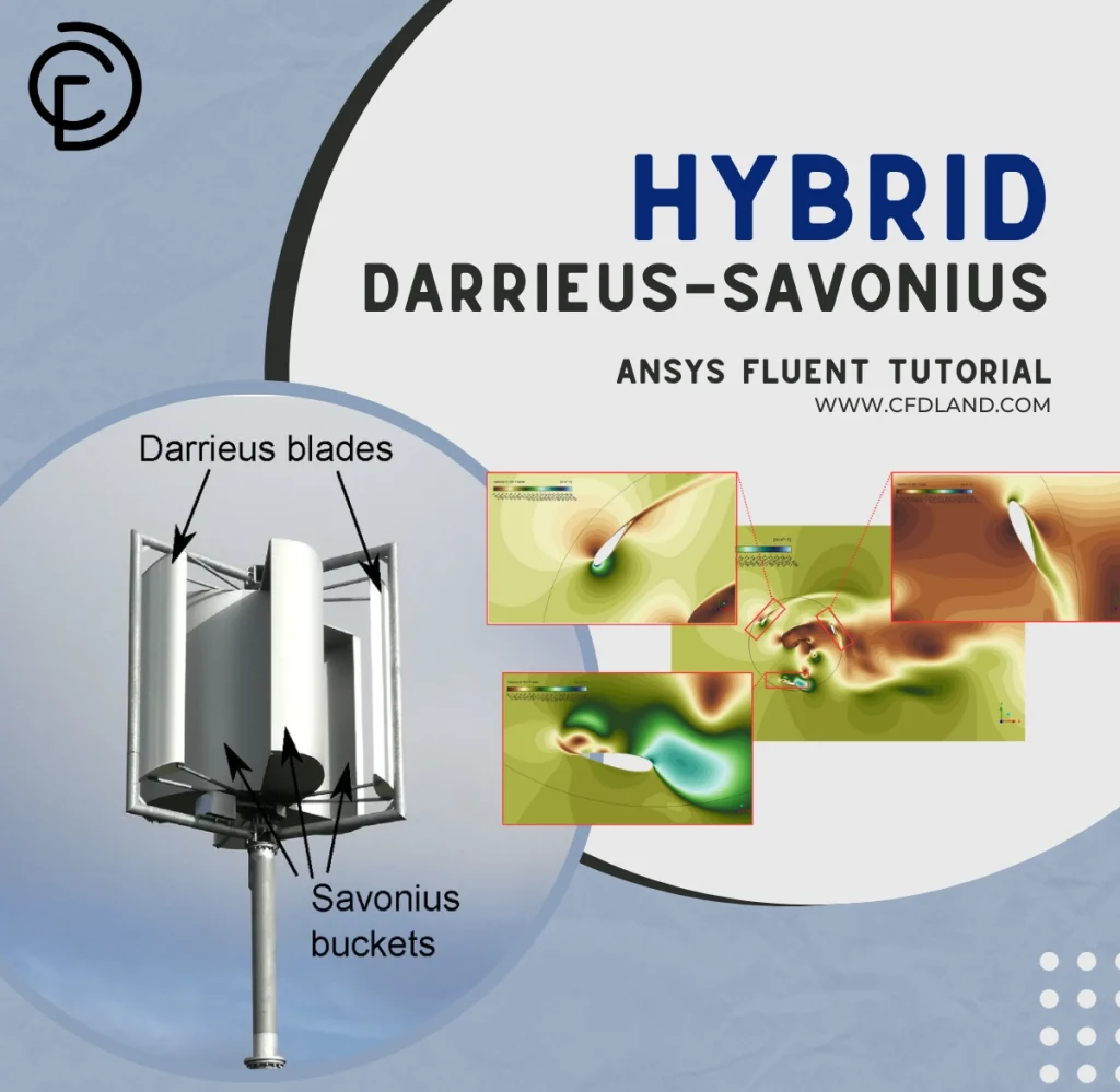
Figure 28- Savonius vertical axis wind turbine, effect of turbulence models in fluent: Turbomachinery example in ANSYS Fluent
Performance and Efficiency Prediction
- Fluent can calculate critical performance indicators:
- Head, flow rate, power input/output
- Hydraulic, mechanical, and overall efficiency
- Torque, pressure loss, and cavitation zones

Figure 29- Centrifugal Pump Impeller FSI CFD: ANSYS Fluent turbomachinery tutorial
Cavitation and Multiphase Flow
Cavitation can damage turbomachinery. Fluent supports:
- Cavitation models (e.g., Schnerr–Sauer) to predict vapor formation
- Multiphase flow models (Eulerian, VOF, Mixture) for liquid-gas or gas-solid flows
- Useful for pumps, marine propellers, and turbines operating in varying fluid conditions

Figure 30- Multiphase flow role in ANSYS Fluent turbomachinery
Overall, ANSYS Fluent provides an integrated, accurate, and flexible environment for simulating all aspects of turbomachinery performance, from aerodynamic efficiency and cavitation prediction to transient rotor-stator interaction and thermal behavior. These capabilities help engineers reduce prototyping costs, enhance reliability, and improve overall machine performance through simulation-driven design.
CFDLAND Expertise in Turbomachinery Modeling Using ANSYS Fluent
At CFDLAND, our experts specialize in the accurate and efficient simulation of all types of turbomachines using ANSYS Fluent. You can rely on us to deliver high-quality results—submit your project through the Order Project page and experience the precision and excellence we bring to every simulation.
We’ve successfully completed a wide range of turbomachinery projects, many of which are showcased above. Explore them—you might find exactly what you’re looking for. You can also visit our CFD Shop to see detailed examples of our simulations across various CFD applications.