
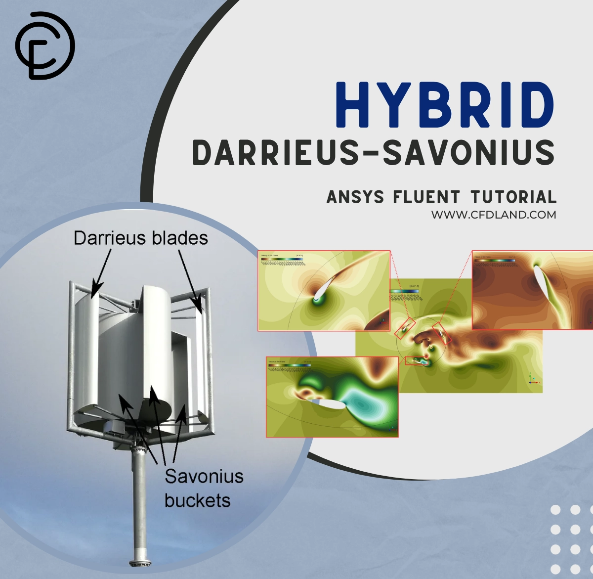


A Hybrid Darrieus-Savonius Vertical Axis Wind Turbine (VAWT) strategically merges two distinct aerodynamic principles onto a single rotational axis. The central Savonius rotor utilizes a drag-based design to provide critical self-starting capabilities at low wind speeds. Conversely, the outer Darrieus airfoils rely on lift to maximize power generation at higher rotational velocities. However, physically combining these rotors creates a severe aerodynamic penalty. The internal Savonius rotor acts as a blunt body, shedding massive, low-velocity turbulent wakes directly into the path of the highly sensitive Darrieus blades.
To resolve this interference and optimize the system’s total power coefficient, engineers must perform a highly advanced Hybrid Darrieus-Savonius CFD analysis. By strictly evaluating the transient flow physics, designers can determine the exact azimuthal placement that minimizes wake collisions. In this comprehensive ANSYS Fluent tutorial, we demonstrate the physical results of this fluid-structure interaction. For engineers seeking to bypass years of trial and error in VAWT design, mastering this specific computational methodology is essential for accurately calculating cyclic aerodynamic loads. In case you`re looking for more tutorials about Renewable Energy CFD studies, check our library.
- Reference: Inácio, Rhuandrei Gabriel da Silva, et al. “Numerical Investigation of Hybrid Darrieus/Savonius Vertical Axis Wind Turbine Subjected to Turbulent Airflows.” Journal of Marine Science and Engineering10 (2025): 1979.
Figure 1: view of hybrid turbine; view of Darrieus turbine and view of Savonius turbine
Simulation Process: Sliding Mesh Interface & k-omega SST Setup
To capture the physical behavior of the rotating system, the computational domain relies on a highly refined mesh consisting of 504,962 hybrid elements. The geometry encloses both the Darrieus rotor (diameter 800 mm, utilizing NACA 0018 airfoils) and the central Savonius drum (diameter 320 mm). To physically simulate the continuous rotation at exactly 20 rad/s, the solver utilizes a Sliding Mesh transient formulation. Rather than using simplified rotating reference frames, the sliding mesh physically rotates the inner computational zone at every timestep, allowing the solver to strictly track the shed vortices as they travel across the boundary interface into the stationary far-field.
Furthermore, accurately predicting VAWT performance requires strict adherence to advanced turbulence modeling. Because vertical blades constantly change their angle of attack relative to the wind, they experience massive flow separation and dynamic stall. The setup specifically deploys the k-omega SST (Shear Stress Transport) turbulence model. This mathematical formulation is strictly required to resolve the near-wall viscous boundary layers on the blades while simultaneously tracking the turbulent dissipation in the wake. The downloadable tutorial details the exact solver settings and timestep sizes required to maintain numerical stability during these violent aerodynamic shifts.
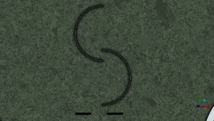
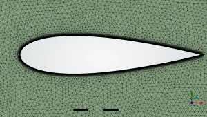
Figure 2: Hybrid grid generation highlighting the severe mesh refinement required to resolve the boundary layers around both the Darrieus and Savonius surfaces.
Post-processing: Transient Torque Analysis & Wake Interactions
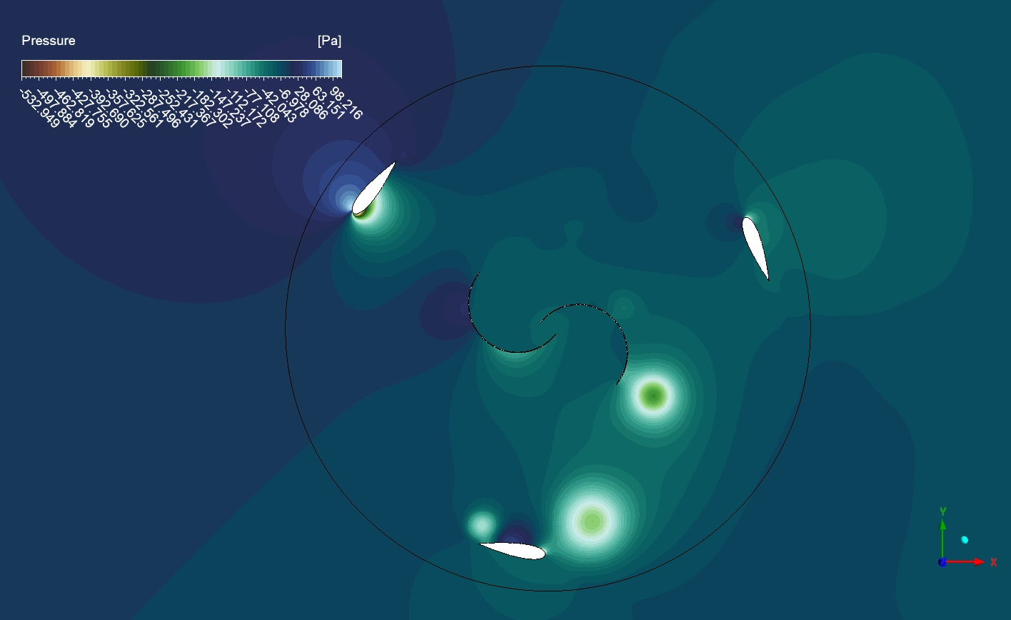
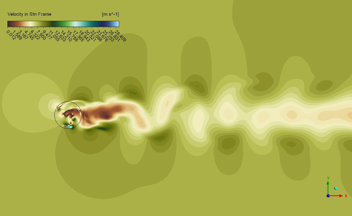
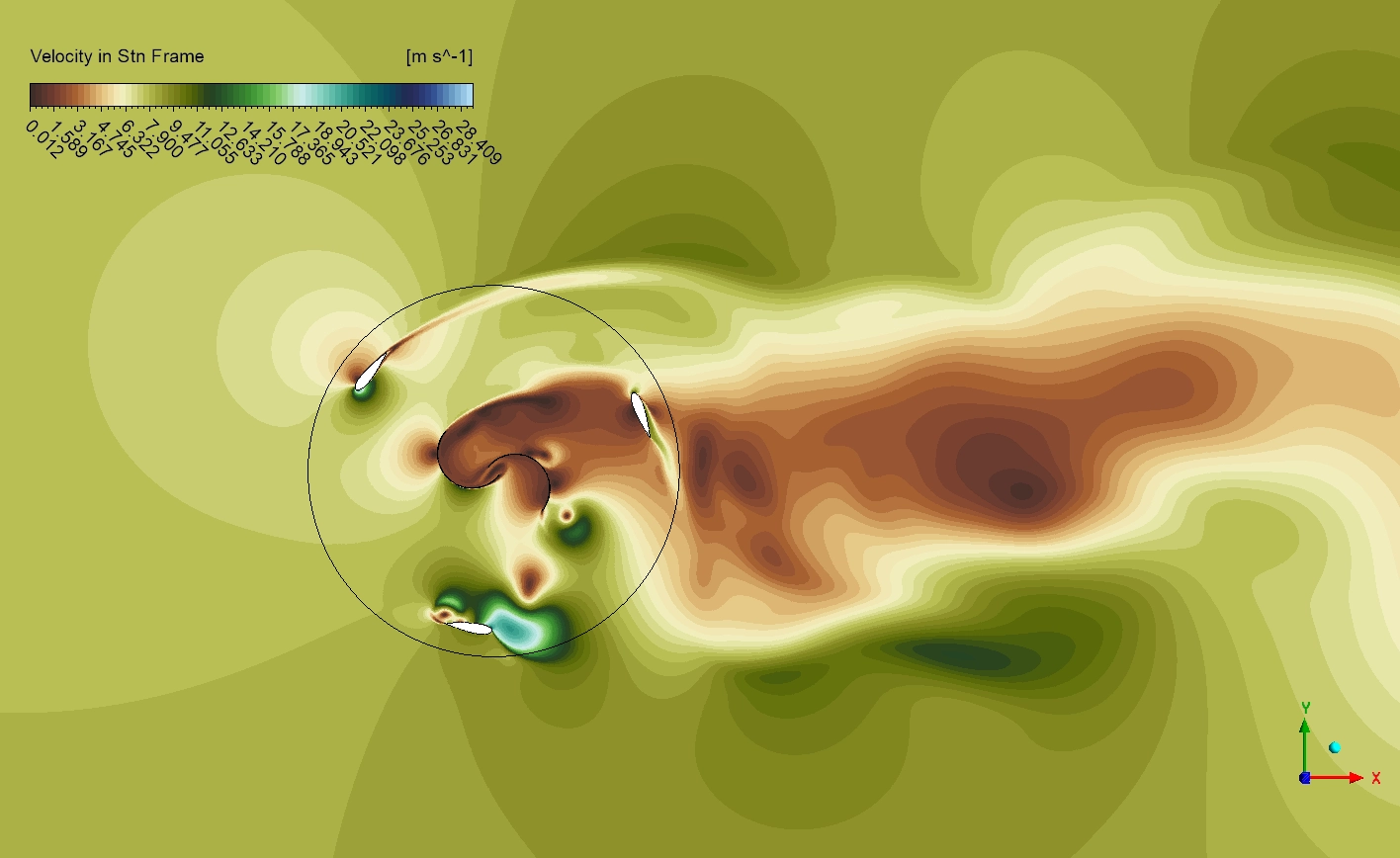
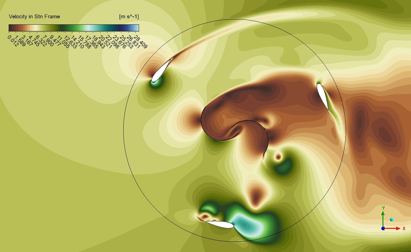
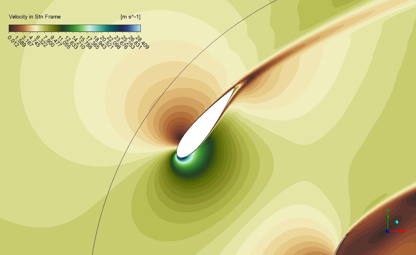
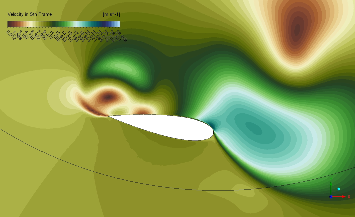
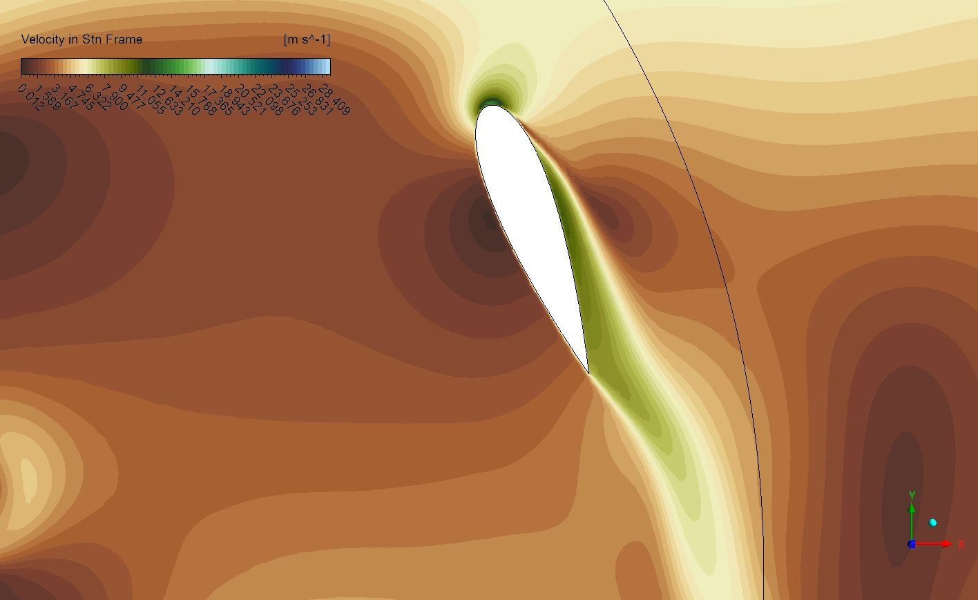
The visual data extracted from the ANSYS Fluent solver mathematically proves the immense difficulty of operating a hybrid turbine. The instantaneous velocity contour tracks the fluid acceleration over the convex suction side of the Darrieus blades, reaching an absolute maximum velocity of exactly 28.4m/s, as dictated by the visual legend. Immediately downstream of the central axis, the Savonius rotor generates a dense, low-velocity wake. When the outer Darrieus blades physically sweep through this disturbed fluid, they instantly lose their aerodynamic lift, resulting in massive performance drops.
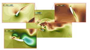
Figure 3: Instantaneous velocity contour tracking flow acceleration over the Darrieus airfoils (peaking at strictly 28.409 m/s) and the subsequent low-velocity interference wake generated by the Savonius drum.
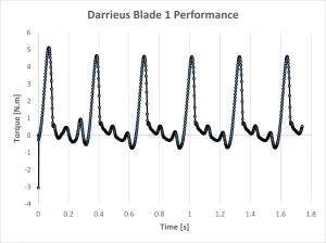
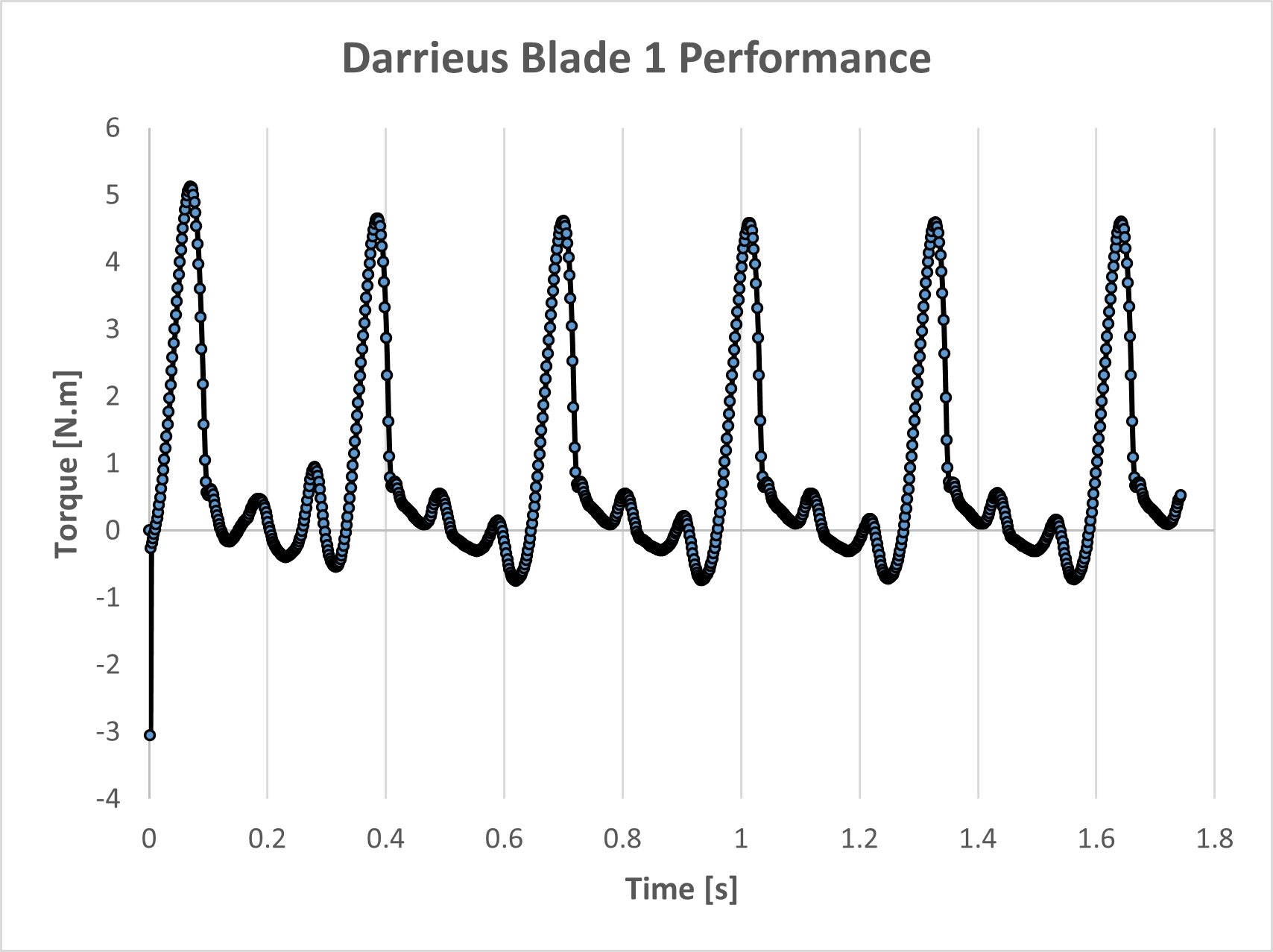
Figure 4: Transient torque performance of Darrieus Blade 1, mathematically proving the extreme aerodynamic oscillation between -1.0 N·m and 5.1 N·m due to changing angles of attack.
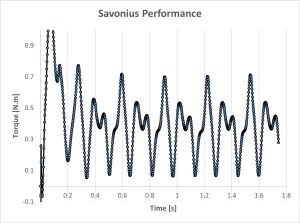
Figure 5: Transient torque performance of the internal Savonius rotor, displaying a consistent, positive drag-based driving force peaking near 0.98 N·m.
This instability is strictly quantified in the transient torque data. The central Savonius rotor acts as a consistent drag component, providing a reliable, positive periodic driving force that peaks near 0.98 N·m. Conversely, the lift-driven Darrieus blades suffer violent cyclic loads. The exact chart confirms Darrieus Blade 1 rapidly shifts between a negative drag resistance of -1.0 N·m (deep stall) and a positive lift generation peaking slightly above 5.1 N·m.
By evaluating the Turbulence Kinetic Energy (TKE) contour, we can mathematically pinpoint the exact locations of these boundary layer separations. The exact visual legend confirms the absolute maximum turbulent energy generated within the interacting wakes reaches strictly 6.543 m²/s². Based on these intense transient interactions, the total averaged physical performance of this specific configuration yields a system Power Coefficient (Cp) of 0.127.
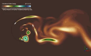
Figure 6: Turbulence Kinetic Energy contour proving intense vortex shedding and flow separation, with the maximum turbulent energy reaching exactly 6.543 m²/s² directly downstream.
Data Table: Hybrid VAWT Aerodynamic Performance
| Aerodynamic Parameter | CFD Calculated Value |
| System Power Coefficient (Cp) | 0.127 |
| Rotational Velocity | 20 rad/s |
| Blade 1 Average Torque | 0.76 N·m |
| Blade 2 Average Torque | 0.45 N·m |
| Blade 3 Average Torque | 0.40 N·m |
| Savonius Average Torque | 0.377 N·m |
Frequently Asked Questions (FAQ)
- Why does the Darrieus blade experience a massive negative torque of -1.0 N·m?
- Vertical axis blades continuously alter their angle of attack relative to the wind direction. When rotating through the upwind or downwind dead zones, or when colliding with the turbulent Savonius wake, the airfoil enters deep stall. During this phase, it generates severe drag rather than lift, resisting the rotation of the shaft.
- What is the specific function of the Sliding Mesh formulation in ANSYS Fluent?
- Unlike steady-state approximations, the Sliding Mesh technique physically rotates the interior mesh zone at 20 rad/s during every transient solver timestep. This exact mathematical process allows the complex wake generated by the inner Savonius rotor to naturally travel outward and interact with the passing Darrieus blades.
- Why is there a discrepancy in the average torque between the three Darrieus blades?
- The data shows Blade 1 averaging 0.76 N·m, while Blades 2 and 3 drop to 0.45 N·m and 0.40 N·m. This discrepancy mathematically proves asymmetric wake interference. Depending on their specific phase angle, certain blades spend more time trapped in the low-velocity, high-turbulence wake shed by the central Savonius rotor, destroying their lifting capacity.


Reviews
There are no reviews yet.