


Radiation Heat Transfer
Have you ever wondered how the Sun heats the Earth despite being millions of kilometers away in the vacuum of space? The answer lies in radiation—the transfer of energy through electromagnetic waves or photons caused by changes in the electron configurations of atoms or molecules. More specifically, thermal radiation is the energy emitted by matter at any temperature above absolute zero, whether it’s a solid, liquid, or gas. Unlike conduction and convection, which need a material to travel through, radiation works perfectly even in a vacuum. In fact, it’s the most efficient method of heat transfer in space—delivering sunlight across millions of kilometers at the speed of light.
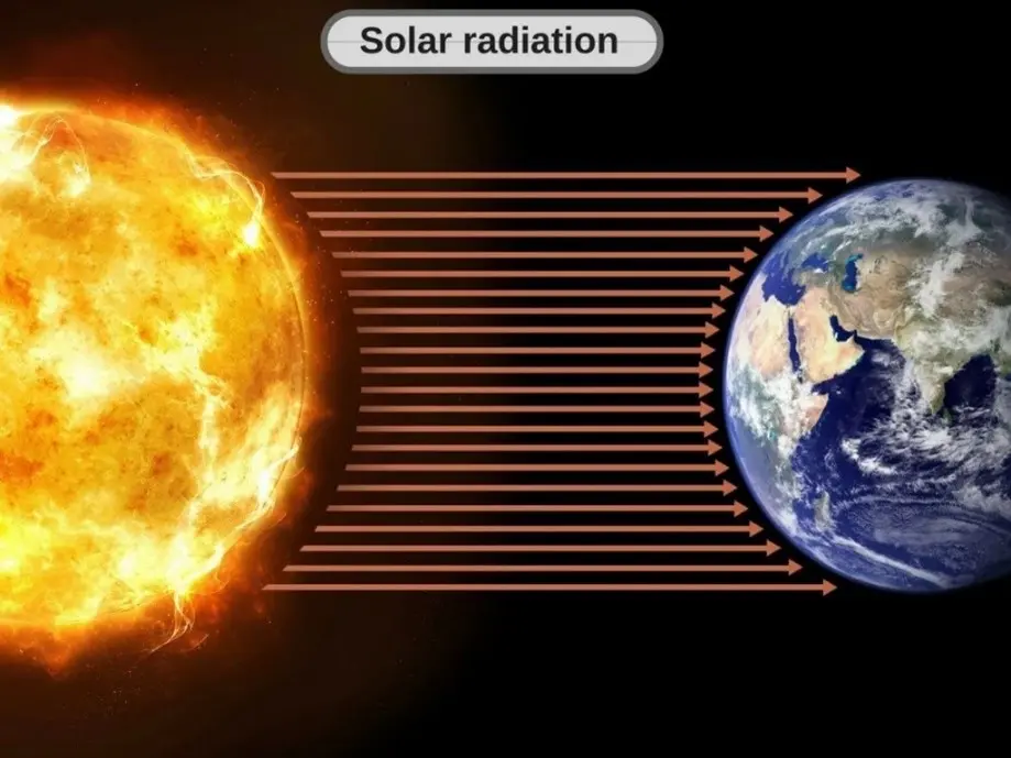
Figure 1- How Does Heat Travel from the Sun through Space or Vacuum?
Stefan-Boltzmann Law
Although radiation occurs throughout the volume of solids, liquids, and gases—since all forms of matter can emit, absorb, or transmit it to some extent—it’s often treated as a surface phenomenon for opaque solids like metals, wood, or stone. That’s because, in such materials, radiation from deeper layers cannot escape to the surface, and incoming radiation is absorbed within just a few microns of the outer layer. The maximum possible rate of radiation from a surface at temperature Ts (in Kelvin or Rankine) is defined by the Stefan–Boltzmann law:

here, sigma is the Stefan–Boltzmann constant. It should be noted that a surface that radiates energy at this maximum rate is known as a blackbody, and the energy it emits is called blackbody radiation. In reality, however, actual surfaces emit less radiation than a blackbody at the same temperature. This is represented by:

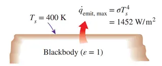
Figure 2- Blackbody radiation represents the maximum amount of radiation that can be emitted from a surface at a specified temperature
The term ε is called emissivity, ranging between 0 and 1, and indicates how efficiently a surface emits radiation compared to a blackbody. A perfect blackbody has ε=1. The emissivity of some surfaces are given in Fig.3
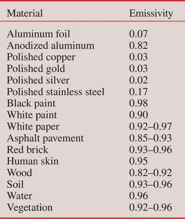
Figure 3- Emissivity of some materials at 300 K
Blackbody Radiation
Have you ever wondered how much radiation a surface can emit at a certain temperature? To explore this, scientists use an idealized concept called a blackbody—a perfect emitter and absorber of electromagnetic radiation. A blackbody absorbs all incident radiation (with no reflection or transmission) and emits the maximum possible energy at a given temperature and wavelength. While no real surface behaves exactly like a blackbody, some materials and specially designed cavities can closely approximate its behavior. Best physical approximation of a blackbody is a cavity with a small hole and uniform internal temperature (Fig.4).
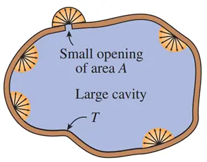
Figure 4- A large isothermal cavity at temperature T with a small opening of area A closely resembles a blackbody of surface area A at the same temperature.
Key properties of a blackbody:
- Absorbs all incident radiation, regardless of direction or wavelength
- Emits the maximum radiation possible for a given temperature
- Is a diffuse emitter (emits uniformly in all directions)
- Appears black because it absorbs visible light completely
- Real surfaces always emit less than a blackbody
- Can be approximated with coatings like black gold, black platinum, or graphite
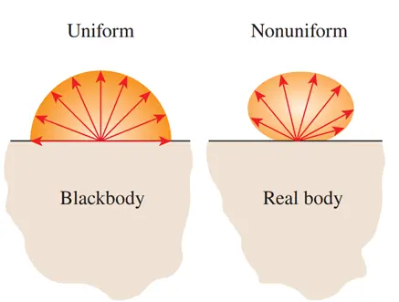
Figure 5- A blackbody is said to be a diffuse emitter since it emits radiation energy uniformly in all directions.
Absorptivity
Absorptivity (α) is a key radiation property that represents the fraction of incident radiation absorbed by a surface, with values ranging from 0 (no absorption) to 1 (complete absorption). When radiation strikes a surface, some of it may be absorbed—raising the thermal energy of the material—while the rest is either reflected or, if the surface is semitransparent, transmitted. Unlike absorption, reflection and transmission do not change the thermal energy of the material. For opaque surfaces, only absorption and reflection occur. The value of absorptivity depends not only on the material and surface characteristics but also on the nature of the incident radiation, such as its wavelength and source. For example, a surface may have different absorptivity for solar radiation compared to radiation from a hot furnace.
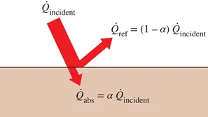
Figure 6- The absorption of radiation incident on an opaque surface of absorptivity α.
Kirchhoff’s law of radiation states that the emissivity and the absorptivity of a surface at a given temperature and wavelength are equal. In many practical applications, the surface temperature and the temperature of the source of incident radiation are of the same order of magnitude, and the average absorptivity of a surface is taken to be equal to its average emissivity.
Radiation heat transfer between a surface and surrounding
When a surface of emissivity ε and surface area As at a thermodynamic temperature Ts is completely enclosed by a much larger (or black) surface at thermodynamic temperature Tsurr separated by a gas (such as air) that does not intervene with radiation, the net rate of radiation heat transfer between these two surfaces is given by:

In this special case, the emissivity and the surface area of the surrounding surface do not have any effect on the net radiation heat transfer and ε= α.
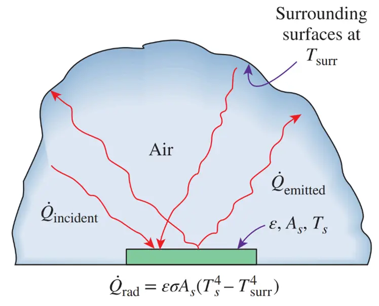
Figure 7- Radiation heat transfer between a surface and the surfaces surrounding it.
Radiation heat transfer to or from a surface surrounded by a gas such as air occurs parallel to conduction (or convection, if there is bulk gas motion) between the surface and the gas. Thus the total heat transfer is determined by adding the contributions of both heat transfer mechanisms. For simplicity and convenience, this is often done by defining a combined heat transfer coefficient hcombined that includes the effects of both convection and radiation. Then the total heat transfer rate to or from a surface by convection and radiation is expressed as:


Atmospheric and Solar Radiation
The solar energy incident on a surface on Earth consists of two main components: direct solar radiation and diffuse solar radiation. Direct solar radiation (GD) is the portion of sunlight that travels in a straight path from the sun to the Earth’s surface without being scattered or absorbed by atmospheric particles. In contrast, diffuse solar radiation (Gd) results from sunlight that is scattered by molecules, aerosols, and clouds in the atmosphere and reaches the surface from all directions. The total solar radiation (Gsolar) on a horizontal surface is the sum of these two components:

where θ is the angle of incidence of direct solar radiation (the angle that the sun’s rays make with the normal of the surface). The diffuse radiation varies from about 10 percent of the total radiation on a clear day to nearly 100 percent on a totally cloudy day.
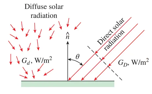
Figure 8- Difference between direct radiations and diffuse radiation on a horizontal surface on earth’s surface.
Absorptivity, Reflectivity, and Transmissivity
Everything around us constantly emits radiation, and the emissivity represents the emission characteristics of those bodies. This means that everybody, including our own, is constantly bombarded by radiation coming from all directions over a range of wavelengths. Recall that radiation flux incident on a surface is called irradiation and is denoted by G. When radiation strikes a surface, part of it is absorbed, part of it is reflected,
and the remaining part, if any, is transmitted, as illustrated in Fig. 9.
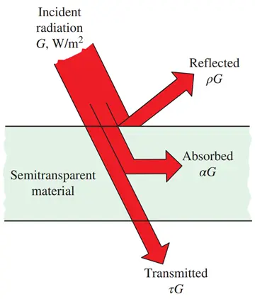
Figure 9- The absorption, reflection, and transmission of incident radiation by a semitransparent material.
The fraction of irradiation absorbed by the surface is called the absorptivity α, the fraction reflected by the surface is called the reflectivity ρ, and the fraction transmitted is called the transmissivity τ. That is,


where G is the radiation flux incident on the surface, and Gabs, Gref, and Gtr are the absorbed, reflected, and transmitted portions of it, respectively. The first law of thermodynamics requires that the sum of the absorbed, reflected, and transmitted radiation be equal to the incident radiation. That is,
G =Gabs+ Gref + Gtr
These three properties are related by the conservation of energy: α+ρ+τ= 1. For opaque surfaces (like most solids), transmissivity (τ) = 0, so the relationship simplifies to: α+ρ=1. Understanding these surface properties is essential in CFD radiation modeling, especially when using tools like ANSYS Fluent radiation heat transfer simulations. Engineers define these parameters precisely when setting radiation boundary conditions in Fluent to ensure accurate predictions of heat exchange in real-world applications.
Simulation of Radiation Heat Transfer by ANSYS Fluent
ANSYS Fluent is a powerful computational fluid dynamics (CFD) software based on the finite volume method, renowned for its ability to simulate radiation heat transfer with high accuracy. It enables engineers to model all major heat transfer modes—conduction, convection, and thermal radiation—simultaneously within complex systems. One of Fluent’s key strengths lies in its precise handling of CFD radiation models, allowing detailed definitions of radiation boundary conditions, surface emissivity, and participation in radiative exchanges. Whether simulating fluent surface-to-surface radiation or fluent solar radiation, engineers can optimize thermal performance in components ranging from industrial furnaces to spacecraft and solar energy systems. This makes ANSYS Fluent radiation heat transfer simulations an essential tool for developing efficient, reliable thermal designs in advanced engineering applications.
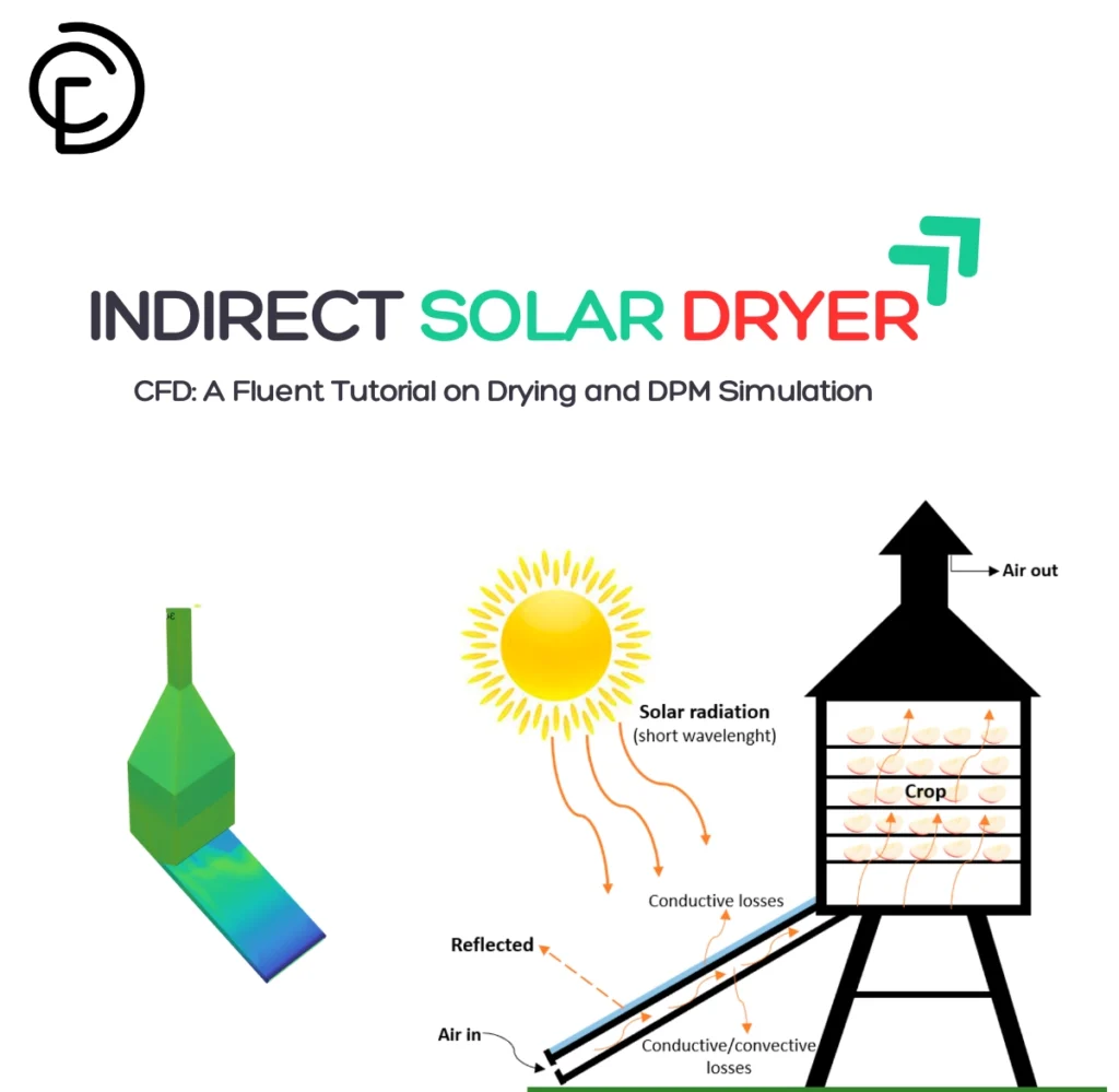
Figure 10-Temperature contour, adopted from “Active Cooling in Photovoltaic System CFD Simulation”: CFD LAND ANSYS Fluent radiation tutorial
Radiation Heat Transfer Equation in ANSYS Fluent
The Radiative Transfer Equation (RTE) describes how radiation propagates through a participating medium that absorbs, emits, and scatters thermal radiation. For a medium at position vector r and in the direction s RTE is expressed as:

Where:
- I(\vec{r}, \vec{s}): Radiation intensity at position \vec{r} in direction \vec{s}
- a: Absorption coefficient
- \sigma_s: Scattering coefficient
- \sigma: Stefan-Boltzmann constant
- T: Local temperature
- n: Refractive index
- \Phi(\vec{s} \cdot \vec{s}’): Scattering phase function
- \vec{s}’: Scattering direction
- d\Omega’: Differential solid angle
- s: Path length along direction \vec{s}
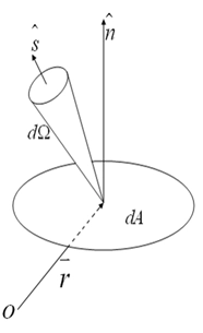
Figure 11-Schematic of energy flow from a surface element
The term (a+σs) represents the optical thickness of the medium, which characterizes how opaque or transparent the medium is to thermal radiation. The refractive index n becomes especially important in semitransparent materials when analyzing radiative behavior. This equation plays a central role in modeling radiation heat transfer in CFD, particularly when using advanced tools like ANSYS Fluent radiation models, including surface-to-surface radiation and solar radiation modeling.
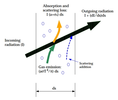
Figure 12- The Schematic of Radiation Heat Transfer Process
Radiation Models in ANSYS Fluent
In thermal and combustion simulations where radiative heat transfer plays a critical role, choosing the right radiation model is essential. ANSYS Fluent provides several radiation models, each with its own assumptions, advantages, and limitations. Below is a comprehensive overview based on the Fig.20.
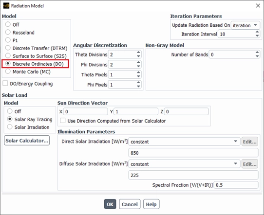
Figure 13- Radiation heat transfer model settings using the Discrete Ordinates (DO) method in ANSYS Fluent.
Rosseland Radiation Model
This model is valid when the optical thickness is high (τ > 3). It simplifies the radiative transfer equation, making it faster than the P-1 model.
| Advantages | Limitations |
| Faster solution time due to fewer equations. | Only valid for optically thick materials. |
| Less memory usage | Only available for the pressure-based solver. |
P-1 Radiation Model
The P-1 model is the simplest approximation of the general P-N method, which expands radiation intensity using spherical harmonics.
| Advantages | Limitations |
| Low computational cost. | Assumes diffuse surfaces. |
| Scattering is included. | Assumes gray radiation. |
| Suitable for combustion applications with high optical thickness. | Accuracy decreases for optically thin media. |
| Can be applied to complex curved geometries. | May overpredict radiation heat flux from sources or sinks. |
DTRM – Discrete Transfer Radiation Model
The Discrete Transfer Radiation Model (DTRM) assumes that radiation emitted from a surface element within a solid angle range can be approximated by a single ray.
| Advantages | Limitations |
| One of the simplest radiation models. | Assumes all surfaces are diffuse. |
| Accuracy increases with the number of rays. | Scattering effects are not included. |
| Applicable over a wide range of optical thicknesses. | Assumes gray radiation. |
| High ray counts require significant computational power. | |
| Not compatible with non-conformal or sliding meshes. | |
| Not suitable for parallel processing. |
S2S – Surface to Surface Radiation Model
This model calculates radiative energy exchange between gray, diffuse surfaces. It uses view factors based on the size, orientation, and position of surfaces.
| Advantages | Limitations |
| Ideal for enclosures without participating media, e.g., spacecraft thermal systems, solar collectors, or engine compartments. | Assumes all surfaces are diffuse. |
| Faster than DTRM and DO, though view factor calculation can be processor-intensive. | Assumes gray radiation. |
| Memory demand increases rapidly with the number of radiating surfaces. | |
| Not suitable for periodic boundary conditions. | |
| Not compatible with non-conformal meshes or symmetric BCs using semi-cube or adaptive view factors. |
DO – Discrete Ordinates Radiation Model
This model solves the Radiative Transfer Equation (RTE) for a finite number of discrete solid angles, each associated with a direction vector in the global Cartesian coordinate system (x, y, z). Unlike DTRM, it does not use ray tracing.
| Advantages | Limitations |
| Valid for all optical thicknesses. | Fine angular discretization can be computationally expensive. |
| Can model surface-to-surface radiation and participating media. | In non-gray radiation, absorption coefficients are assumed constant in each spectral band. |
| Semi-transparent walls can be included. | Emission within each band is also assumed to be constant. |
| Includes scattering and anisotropy. | |
| Moderate computational cost and low memory usage. |
Monte Carlo Radiation Model
Introduced in Fluent version 17, the Monte Carlo method simulates radiation by tracking a large number of rays emitted from surfaces or media.
| Advantages | Limitations |
| Highly accurate for collimated or directional radiation. | Very expensive computationally. |
| Suitable for non-gray media and complex geometries. | Needs large number of rays for statistical accuracy. |
Applications of Radiation Heat Transfer
Radiation heat transfer is a common phenomenon we encounter daily. Sunlight warms the Earth through thermal radiation, while sitting by a fire warms our bodies the same way—by emitting heat directly as radiation. Infrared heaters use this principle to warm people and objects efficiently. Microwave ovens heat food by exciting water molecules with electromagnetic waves. Radiant floor heating systems emit warmth upward from heated surfaces. Heat lamps in restaurants keep food warm using thermal radiation. These examples highlight the important role of radiation heat transfer in our daily lives.
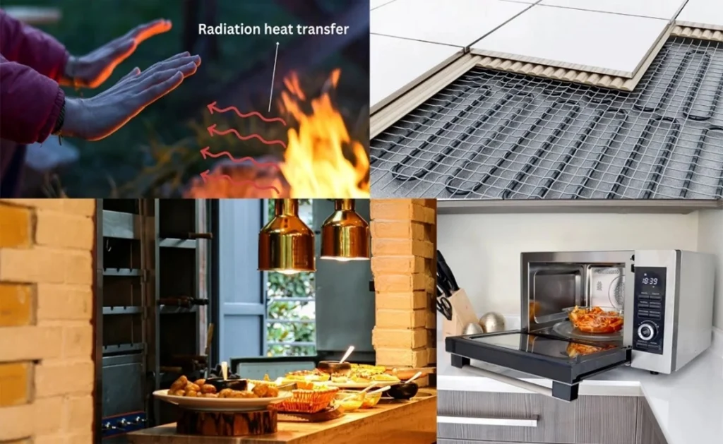
Figure 14- Some application areas of Radiation heat transfer in the daily life.
Spacecraft Thermal Control
In the vacuum of space, radiation heat transfer is the only effective way to regulate temperature. Spacecraft and satellites absorb thermal radiation from the sun and emit heat to maintain balance. Engineers use materials with specific emissivity and absorptivity and rely on CFD radiation models like ANSYS Fluent radiation heat transfer to simulate and optimize performance under extreme conditions.
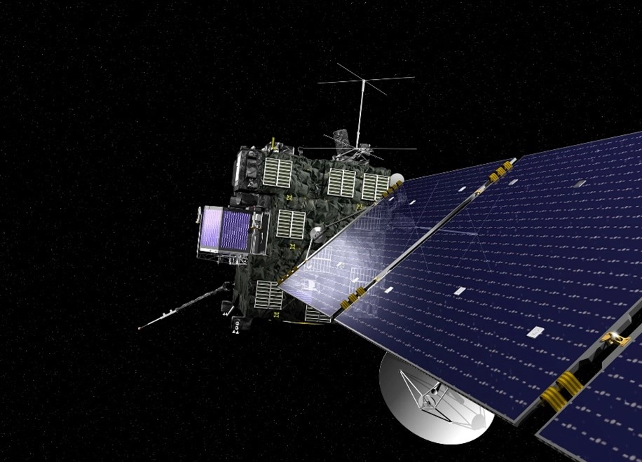
Figure 15- Spacecraft Thermal Control: Applications of Radiation Heat Transfer
Solar Thermal Energy Systems
Radiation heat transfer is the core mechanism in solar thermal power plants. Mirrors or lenses focus sunlight, and thermal radiation heats a working fluid for electricity generation or direct heating. Engineers use CFD radiation models to optimize collector design and enhance efficiency, often using tools like ANSYS Fluent radiation heat transfer for accurate simulation.
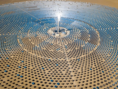
Figure 16- A solar thermal power plant energy farm. By concentrating sunlight with mirrors at one point, the thermal energy is focused on the heat exchanger, increasing the temperature of the fluid.
Building Heating and Cooling
Architects and engineers apply thermal radiation principles to control heat gain and loss in buildings. In cold climates, darker surfaces increase radiation heat transfer by absorbing more solar energy, while lighter materials reflect sunlight in warm areas to keep interiors cooler. Using CFD radiation models like fluent solar radiation and fluent surface to surface radiation, designers optimize building envelopes and HVAC performance for greater energy efficiency.
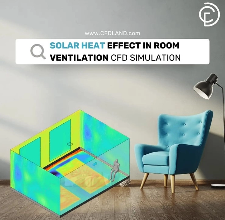
Solar Heat Effect in Room Ventilation CFD Simulation: ANSYS Fluent radiation tutorial
High-Temperature Furnaces and Combustion Chambers
In industrial furnaces and combustion systems, thermal radiation dominates heat transfer due to the extremely high temperatures involved. Surfaces within these systems continuously exchange energy through the radiation heat transfer process, which directly impacts efficiency and fuel usage. Engineers rely on CFD radiation models, including ANSYS Fluent radiation heat transfer, to simulate and control heat distribution, ensuring uniform temperatures and preventing structural damage caused by localized hotspots.
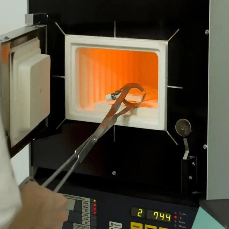
Figure 18- High Temperature Muffle Furnace Manufacturer and Supplier
Medical Laser Treatments
Modern medical treatments utilize thermal radiation generated by lasers to precisely target and destroy harmful cells, such as in cancer therapy. Multiple low-energy laser beams are focused on a single point, where the localized radiation heat transfer raises tissue temperatures enough to achieve therapeutic effects without harming surrounding healthy cells. To ensure accuracy and patient safety, engineers and medical professionals use CFD radiation models and ANSYS Fluent radiation heat transfer simulations to model and optimize these procedures.
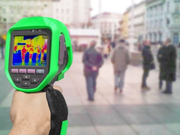
Figure 19- The thermal camera shows the temperature differences of objects by detecting the infrared radiation they emit.
Photovoltaic (PV) systems
Photovoltaic (PV) systems rely heavily on solar radiation to generate electricity, but they are also affected by heat accumulation due to thermal radiation. When PV panels absorb sunlight, only a portion is converted into electricity, while the rest becomes heat. This excess heat can reduce panel efficiency, making radiation heat transfer analysis essential. Engineers use CFD radiation models in tools like ANSYS Fluent to simulate heat buildup and optimize cooling strategies. By understanding and managing the radiation heat transfer process, designers can enhance panel performance and lifespan, especially in large-scale solar farms. Fluent solar radiation modeling is particularly useful for evaluating the impact of geographic location, panel orientation, and material properties on system efficiency.

Figure 20- Photovoltaic Facade of Building CFD Simulation – Experimental Paper Validation: ANSYS Fluent radiation tutorial
CFDLAND Expertise in Radiation Heat Transfer Modeling Using ANSYS Fluent
At CFDLAND, we specialize in advanced radiation heat transfer modeling using ANSYS Fluent software. Our team has successfully completed numerous high-quality CFD radiation simulation projects, many of which are available in our CFDSHOP for immediate use. From Fluent surface to surface radiation to solar radiation modeling, we offer accurate, reliable solutions tailored to your engineering needs. Explore our ready-to-use thermal radiation projects showcased at the top of this page—you might find exactly what you’re looking for. Ready to start your own project? Submit your request through ORDER PROJECT and let our experts deliver exceptional results.