

Ever wonder what happens when four rocket motors fire at the same time? This tutorial shows you how to model 4-cluster rocket motor designs using ANSYS Fluent! Cluster rocket configurations are super important in modern rocket propulsion systems because they help launch bigger payloads. Our step-by-step guide helps you set up a complete CFD simulation of the complex supersonic flow that happens when multiple rocket nozzles fire together at low altitude. You’ll learn how to model the hot rocket exhaust, track dangerous shock waves, and see the fascinating plume interactions between neighboring motors. This exact 4-cluster configuration is used in many real launch vehicles where multiple rocket motors work together to create massive thrust. Using computational fluid dynamics for rocket motor design saves millions in testing costs and helps engineers’ spot problems before they happen. Whether you’re designing your own multi-engine rocket or just want to understand how propulsion systems work, this guide makes complicated rocket CFD easy to understand! We have used multiple reference paper as our guide through this:
- Reference [1]: Mehta, Manish, et al. “Base heating sensitivity study for a 4-cluster rocket motor configuration in supersonic freestream.” 2011 NASA Thermal and Fluids Analysis Workshop (TFAWS 2011). No. M11-0717. 2011.
- Reference [2]: Mehta, Manish, et al. “Numerical base heating sensitivity study for a four-rocket engine core configuration.” Journal of Spacecraft and Rockets3 (2013): 509-526.
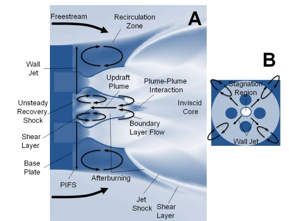
Figure 1: Fluid dynamic structures observed during complex base flows. (A) Side cross-sectional view (B) Top-down sectional view of base plate [1]
Simulation Process
For our 4-cluster rocket motor simulation, we set up a complete model using the compressible flow solver in ANSYS Fluent. Since rocket exhaust reaches incredibly high speeds, we had to use a fully compressible flow approach with the ideal gas law to track changing densities. We built a high-quality mesh in Fluent Meshing with extra refinement around the rocket nozzles and in the exhaust plume interaction regions where shock waves form. The simulation used variable viscosity for air because gas properties change dramatically at the extreme temperatures in rocket propulsion. For the hot rocket exhaust gases, we activated Species Transport to model the complex combustion chemistry that produces the main exhaust components: H2O, CO2, CO, H2, H, OH, O2, and N2.
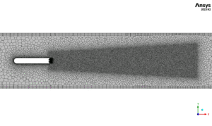
Figure 2: Polyhedra grid generated by Fluent Meshing
Post-processing
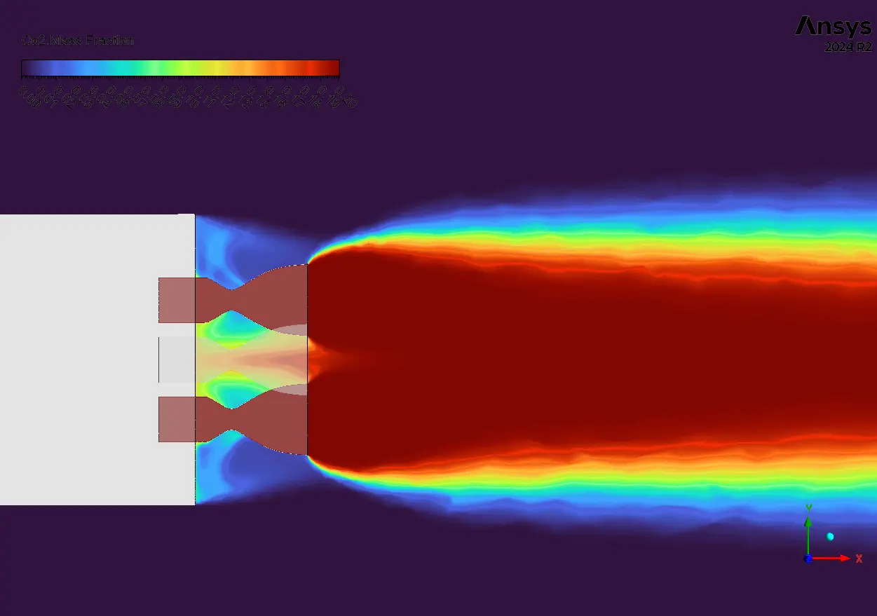
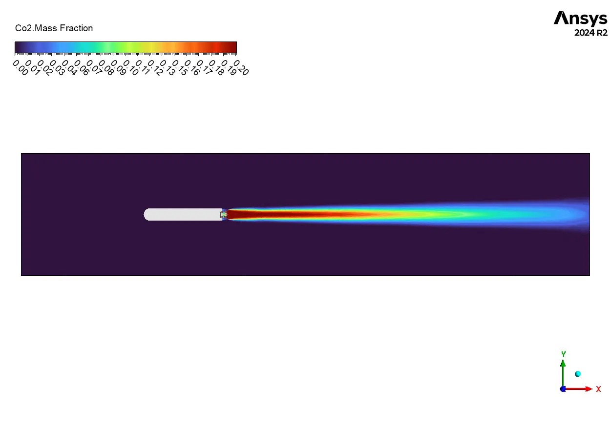
The CO2 mass fraction contours show the complex exhaust plume structure of our 4-cluster rocket motor. The highest CO2 concentration (red regions) appears directly at each rocket nozzle exit, showing where the primary combustion products first emerge. What’s fascinating is how the four individual plumes don’t stay separate – they quickly merge into a single combined exhaust structure. This creates the distinctive recirculation zones we can see forming between adjacent motors (the blue pockets between red streams), exactly matching the patterns shown in Figure 1 of our reference papers. From an engineering perspective, these recirculation regions are critically important for understanding base heating effects in cluster configurations. The CO2 distribution shows significant plume-plume interaction starting very close to the nozzles, which explains why single-engine test data often fails to predict multi-engine rocket behavior. The asymmetric pattern in the outer CO2 boundary layers indicates that the wall jet phenomena described in our reference diagram is accurately captured in our simulation.
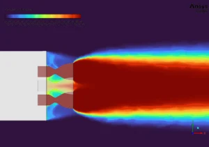
Figure 3: CO2 Mass Fraction Distribution
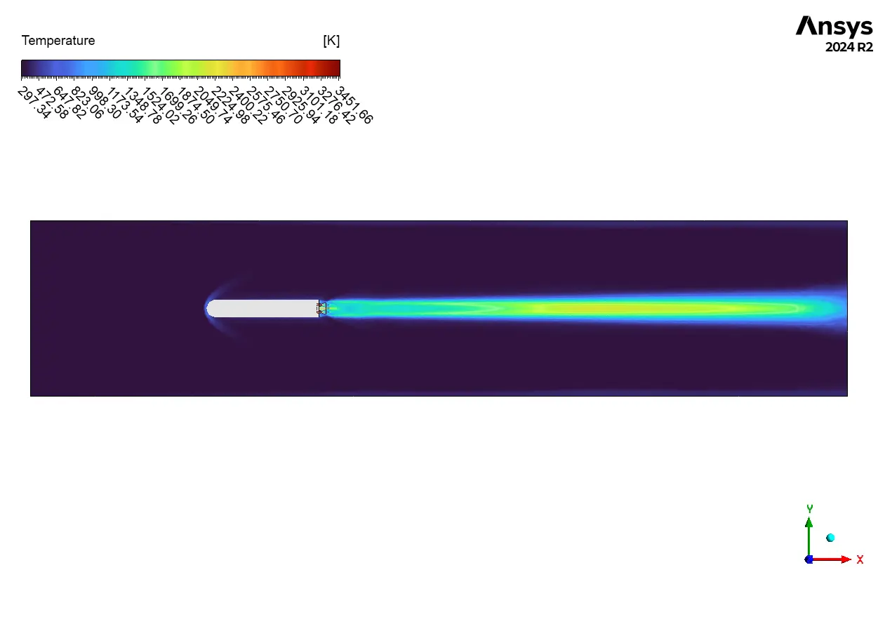
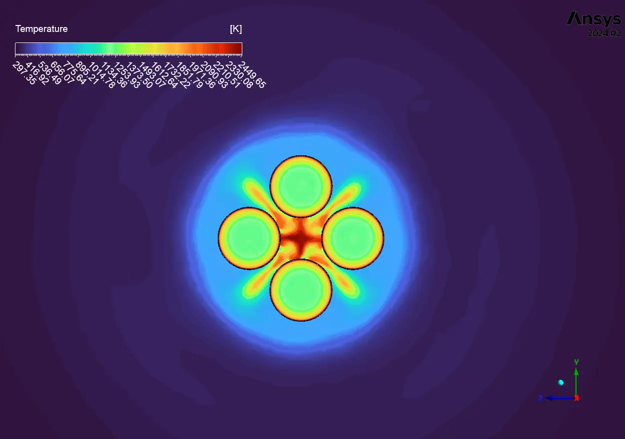
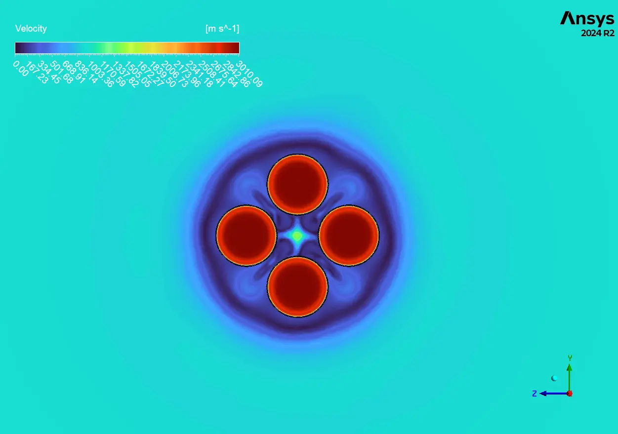
The temperature contours indicate the extreme thermal environment created by our 4-cluster rocket motor. The core regions show temperatures reaching above 3000K (3kK), which matches expected values for typical rocket propulsion systems. The most striking feature is the formation of distinct shock diamonds in each plume – these alternating compression-expansion waves are classic features of supersonic nozzle flow that our simulation captures beautifully. Looking at how the four hot exhaust plumes interact, we can identify the exact stagnation region shown in Figure 1B of our report, where opposing flows meet and create localized high-temperature pockets between motors. These hot spots are particularly concerning for rocket motor designers because they can cause unexpected base heating and material failure. The simulation also reveals significant thermal gradients at the boundary layer between the hot exhaust and ambient air, creating the shear layers annotated in our reference diagram. From a practical perspective, these results explain why clustered rocket configurations often experience more severe thermal issues than single-motor designs – the combined thermal load in the center region exceeds what individual motors would create due to the complex flow interactions that trap hot gases between motors.
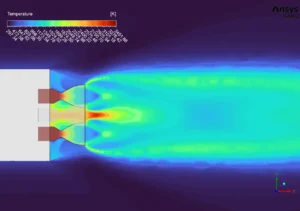

Figure 4: Temperature Distribution
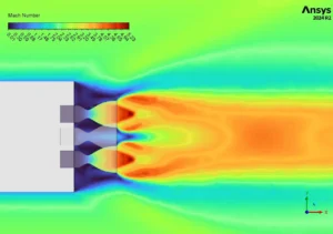
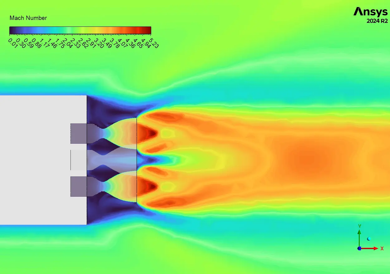
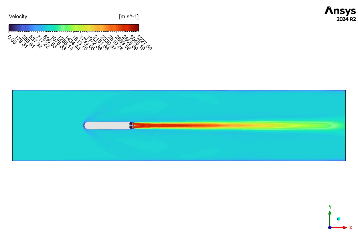
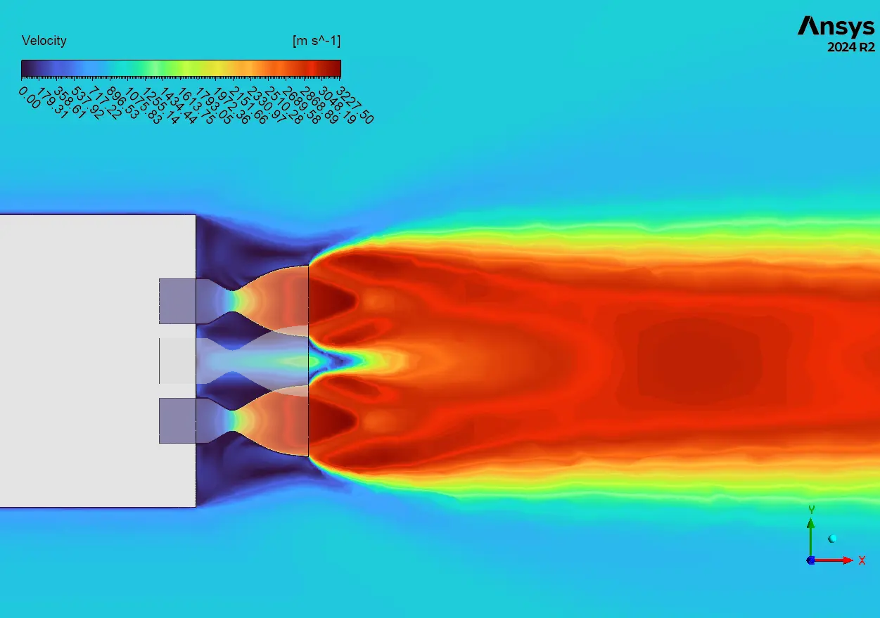
Figure 5: Mach number field indicating supersonic flow


Reviews
There are no reviews yet.