
Gurney flaps are incredibly effective aerodynamic devices that can dramatically improve the performance of airfoils! These small tabs, typically only 1-2% of the chord length, are attached perpendicular to the trailing edge of wings or blades. In this tutorial, we’re expanding our previous studies on pitching airfoils by specifically examining how these clever little flaps modify the complex flow dynamics during oscillation! Building upon our earlier work with standard and slotted airfoils, this new analysis reveals how the Gurney flap creates a significant increase in circulation and delays flow separation during the dynamic motion. Using dynamic mesh techniques and our validated CFD methodology, we captured the formation of distinctive trailing edge vortices that fundamentally alter the pressure distribution around the airfoil. These insights are invaluable for designing more efficient aircraft wings, helicopter rotors, and wind turbine blades that can maintain better performance in unsteady conditions where traditional static airfoil data simply doesn’t apply!
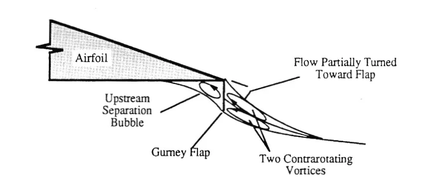
Figure 1: Gurney flap implemented on the trailing edge of the airfoil
Simulation process
For our Gurney flap analysis, we created three distinct geometries: the baseline airfoil and two variants with flap heights of 0.5%c and 1%c at the trailing edge, positioned perpendicular to the chord line. The computational domain was divided into an inner rotating zone containing the airfoil and an outer stationary zone, connected through non-conformal interfaces to facilitate the dynamic mesh motion. We applied our previously validated meshing strategy with refinement regions near the airfoil surface. The pitching motion was implemented through a custom User Defined Function (UDF) that controlled the sinusoidal oscillation. For each case, we simulated 5 complete cycles to ensure the solution reached periodic convergence before recording the final aerodynamic coefficients!
Post-processing
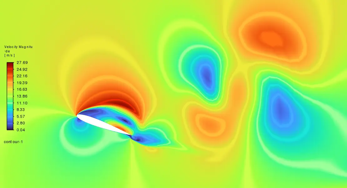
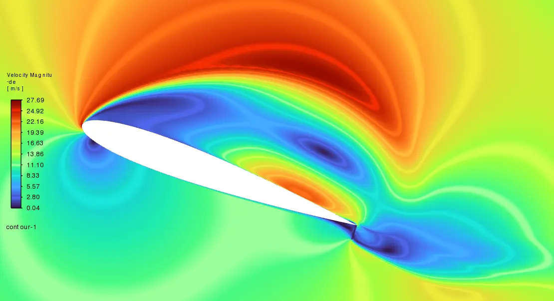
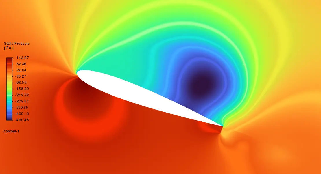
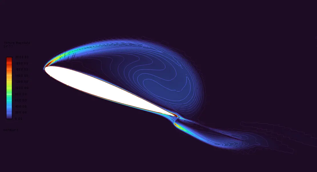
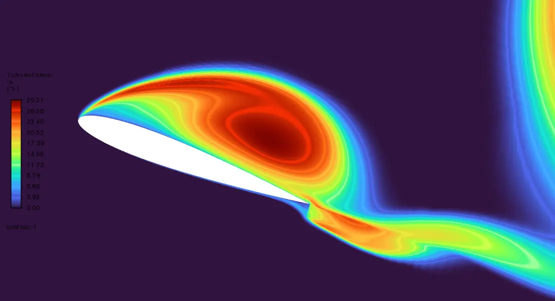
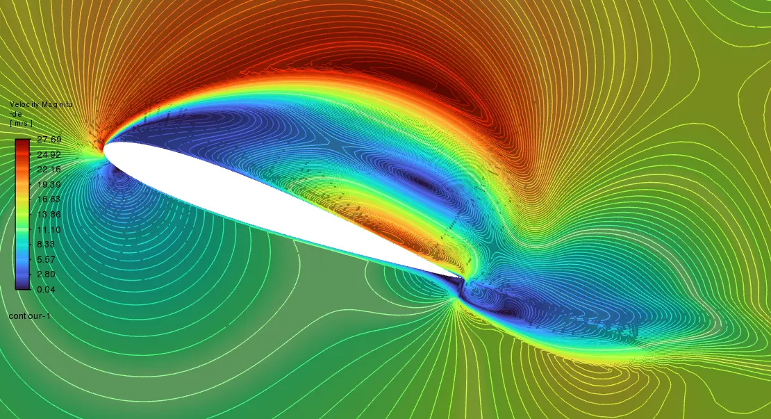
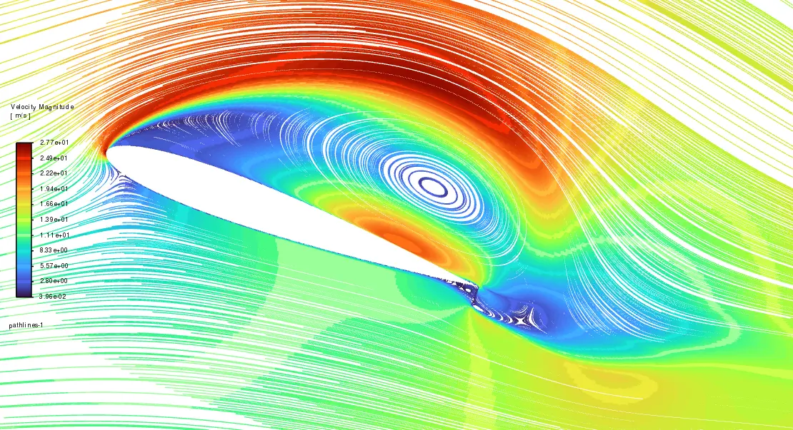
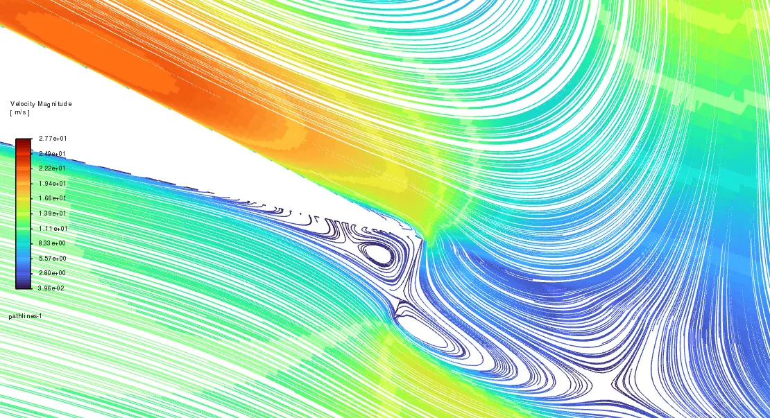
The pressure contours reveal the fascinating aerodynamic mechanism behind the Gurney flap’s effectiveness! As shown in the first image, we observe a dramatic pressure differential between the upper and lower surfaces of the airfoil, with the flap creating an extended low-pressure region (blue area) above the trailing edge while simultaneously increasing pressure below it. This effectively creates a virtual camber increase without physically altering the main airfoil shape! The second image beautifully captures the complex flow physics at work — notice the distinct counter-rotating vortices forming immediately behind the flap, which act as a “pneumatic barrier” that forces the flow to leave the trailing edge at a steeper downward angle. This vortex pair creates a powerful downwash effect that essentially traps the high-momentum flow in the vicinity of the trailing edge, delaying flow separation during the dynamic pitching motion!
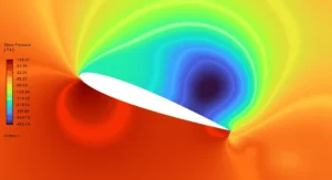
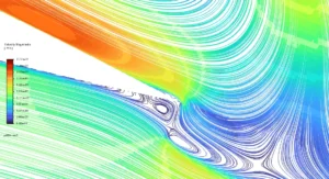
Figure 2: Pressure and streamline visualization around the airfoil with GF
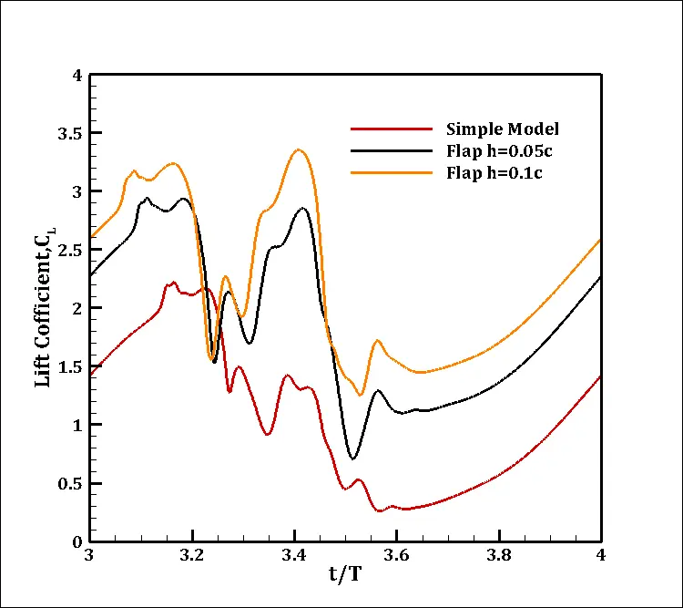
The lift coefficient plot quantitatively confirms these flow phenomena, showing remarkable performance improvements for both flap heights across the pitching cycle! The 0.5%c flap (black line) increases maximum lift by approximately 38% compared to the baseline airfoil, while the 1%c configuration (orange line) achieves an impressive 55% enhancement! Notice how the flapped airfoils maintain substantially higher lift values during the downstroke phase (t/T > 3.5), which indicates superior dynamic stall recovery characteristics. This is attributed to the flap’s ability to stabilize the trailing edge vortex system and provide a consistent downwash effect even during rapid angle changes. The periodic fluctuations visible in all three curves correspond to vortex shedding events, with the flapped configurations showing more controlled shedding patterns and reduced amplitude oscillations — a clear indication of improved aerodynamic stability throughout the pitching motion!
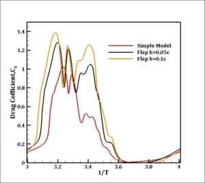
Figure 3: Lift coefficient graph as the airfoil pitching equipped with GF


Reviews
There are no reviews yet.