


Pulse combustion is a combustion process that employs self-sustaining pressure oscillations to improve heat and mass transfer efficiency. In contrast to conventional steady-state combustion, pulse combustion produces intermittent energy bursts that produce pressure waves that enhance fuel-air mixing and elevate combustion intensity. This results in improved thermal efficiencies, lower pollutant emissions, and increased heat transfer rates relative to traditional combustion methods. It is utilized in industrial contexts for processes such as drying, heating, and waste incineration. In addition, Pulse combustion provides multiple benefits; however, it also poses challenges concerning noise, vibration, and system complexity that must be resolved for broader implementation. Similar to all of our studies, this CFD simulation features from a valuable reference paper called “CFD simulation of pulse combustion’s performance [1]”.
- Reference [1]: Rahmatika, Annie Mufyda, et al. “CFD simulation of pulse combustion’s performance.” AIP Conference Proceedings. Vol. 1712. No. 1. AIP Publishing, 2016.

Figure 1: Pulse combustion design configuration [1]
Simulation Process
The chosen pulse combustion type is Helmholtz, featuring a single inlet for a fuel-air mixture, a combustion chamber, and a tailpipe. Given the symmetrical design of it, only half of the domain is created regarding axisymmetric method. The domain is discretized into 25926 structured grid. During the combustion process, fuel and air were injected at a constant speed, while the inlet pulse was introduced at a frequency of 70 Hz using a profile. The propane combustion process utilized the Species Transport Eddy Dissipation approach, as propane was assumed to burn rapidly, similar to most fuels. Consequently, turbulence mixing was considered to have a greater influence on combustion than reaction kinetics.
Propane + O2 ==> Co2 + H2o
Post-processing
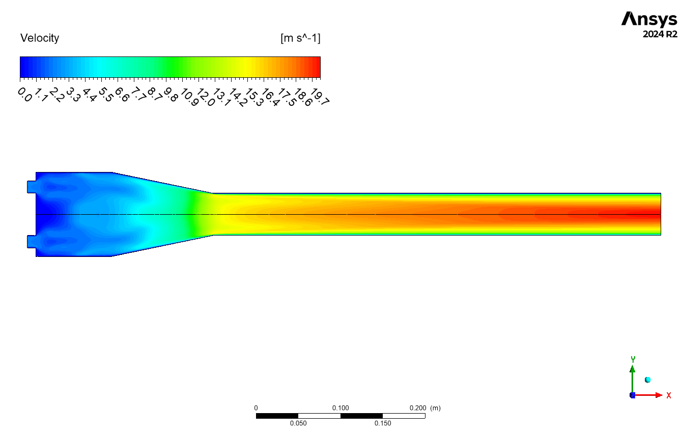
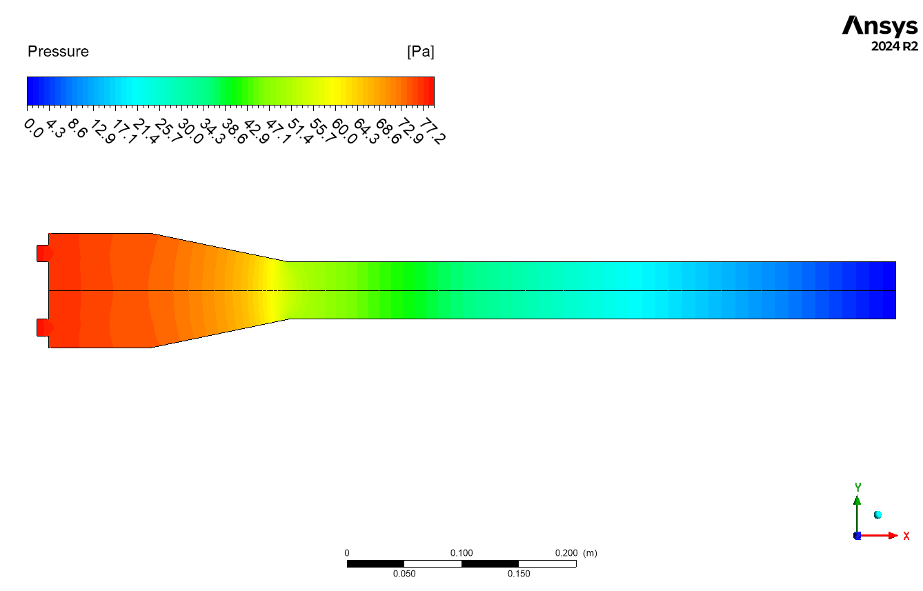
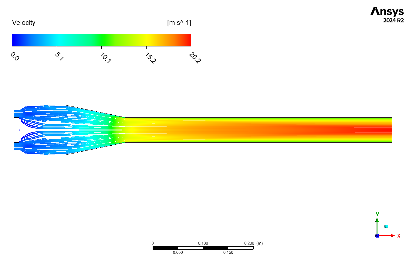
The CFD results demonstrate an exclusive acceleration of flow within the converging nozzle section. The velocity magnitude contours shift from deep red at the inlet to bright yellow as the flow area narrows, implying a substantial increase in fluid velocity. The anticipated acceleration arises from the principle of conservation of mass, whereby a reduction in cross-sectional area requires an increase in velocity to sustain a constant mass flow rate. Maximum velocities occur at the nozzle throat, characterized by the smallest cross-sectional area, achieving approximately 19.7 m/s. The localized high-velocity region is essential for applications such as jet propulsion and industrial cutting, where concentrated kinetic energy is required.
Figure 2: Velocity contour inside pulse combustion CFD simulation
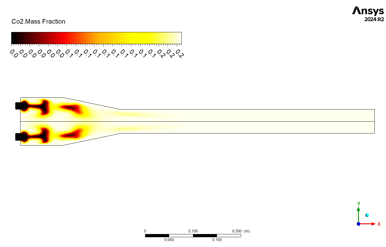
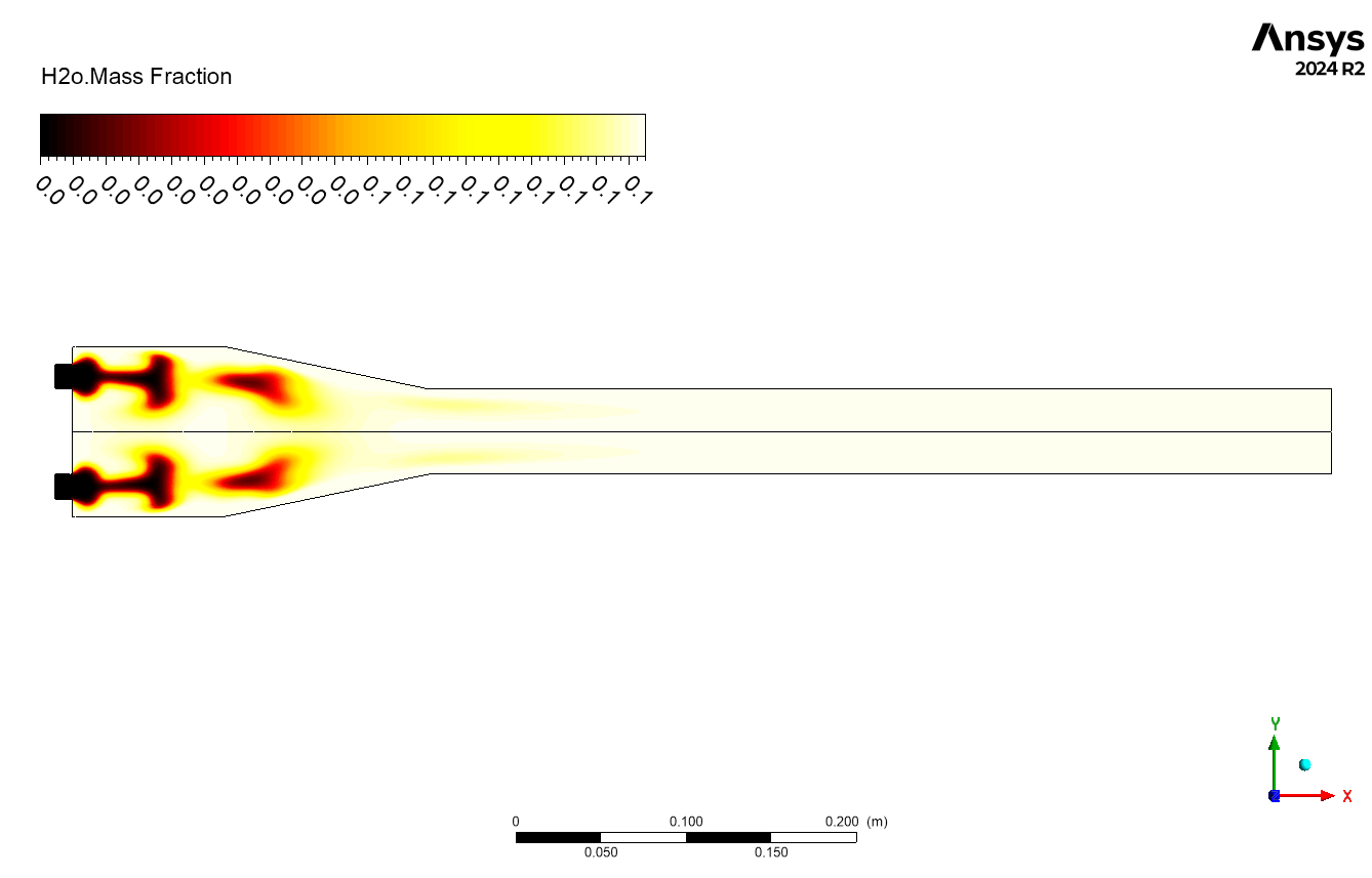
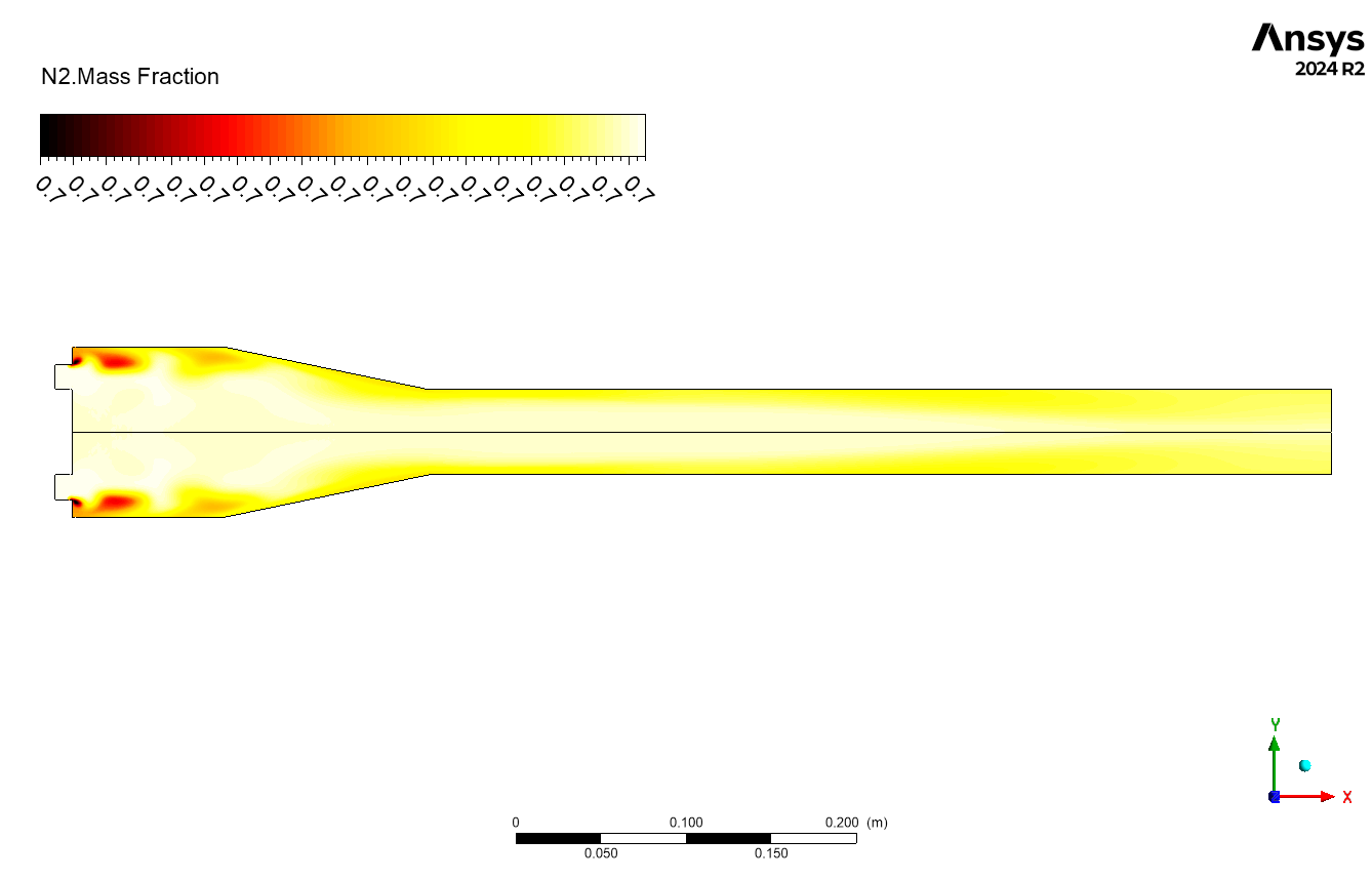
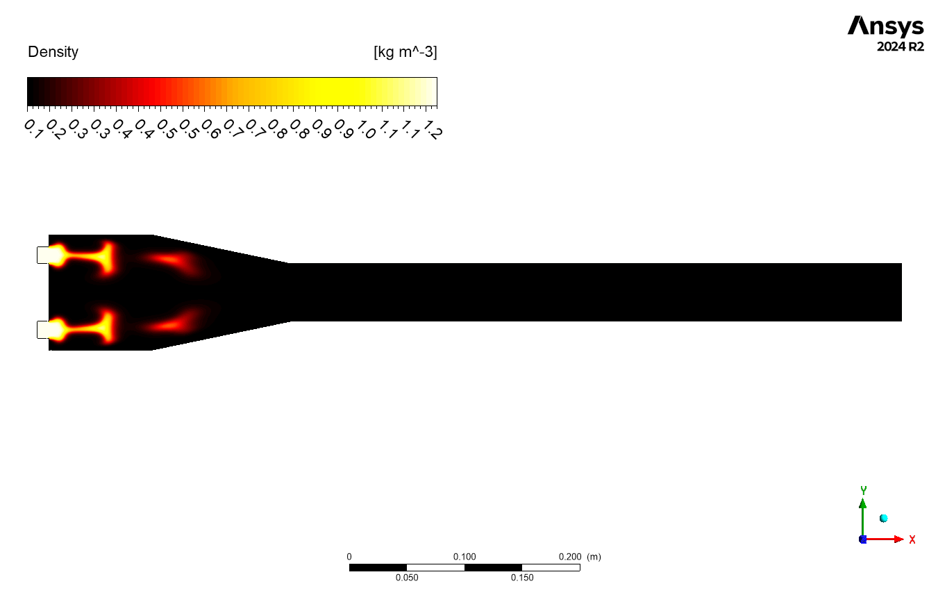
The combustion simulation indicates a peak temperature of around 2850 K, concentrated near the inlets where fuel and air first mix and ignite. The high-temperature region diminishes progressively as the combustion products move downstream, resulting in a more uniform temperature profile near the outlet. The volume-averaged temperature of 1566.31K signifies substantial heat generation and distribution within the combustor. The CO2 mass fraction distribution corresponds to the temperature profile, exhibiting peak concentrations near the inlets and a gradual decline along the flow path. This indicates that the combustion process is predominantly finished near the inlets, with the residual flow mainly comprising the transport and mixing of hot combustion products. The C3H8 mass fraction contours give information about fuel distribution and consumption throughout the combustor. The C3H8 mass percentage at the inlets is nearly zero, indicating rapid fuel consumption in the high-temperature combustion zone. Further downstream, the presence of C3H8 is low, indicating complete combustion and efficient fuel consumption in the system. This efficient combustion, combined with a high average temperature, demonstrates the combustor’s ability to transform chemical energy into thermal energy. The measured temperature and species distributions give useful information for assessing combustor performance.

Figure 3: a) Temperature b)C3H8 distribution inside pulse combustion CFD Simulation


Reviews
There are no reviews yet.