
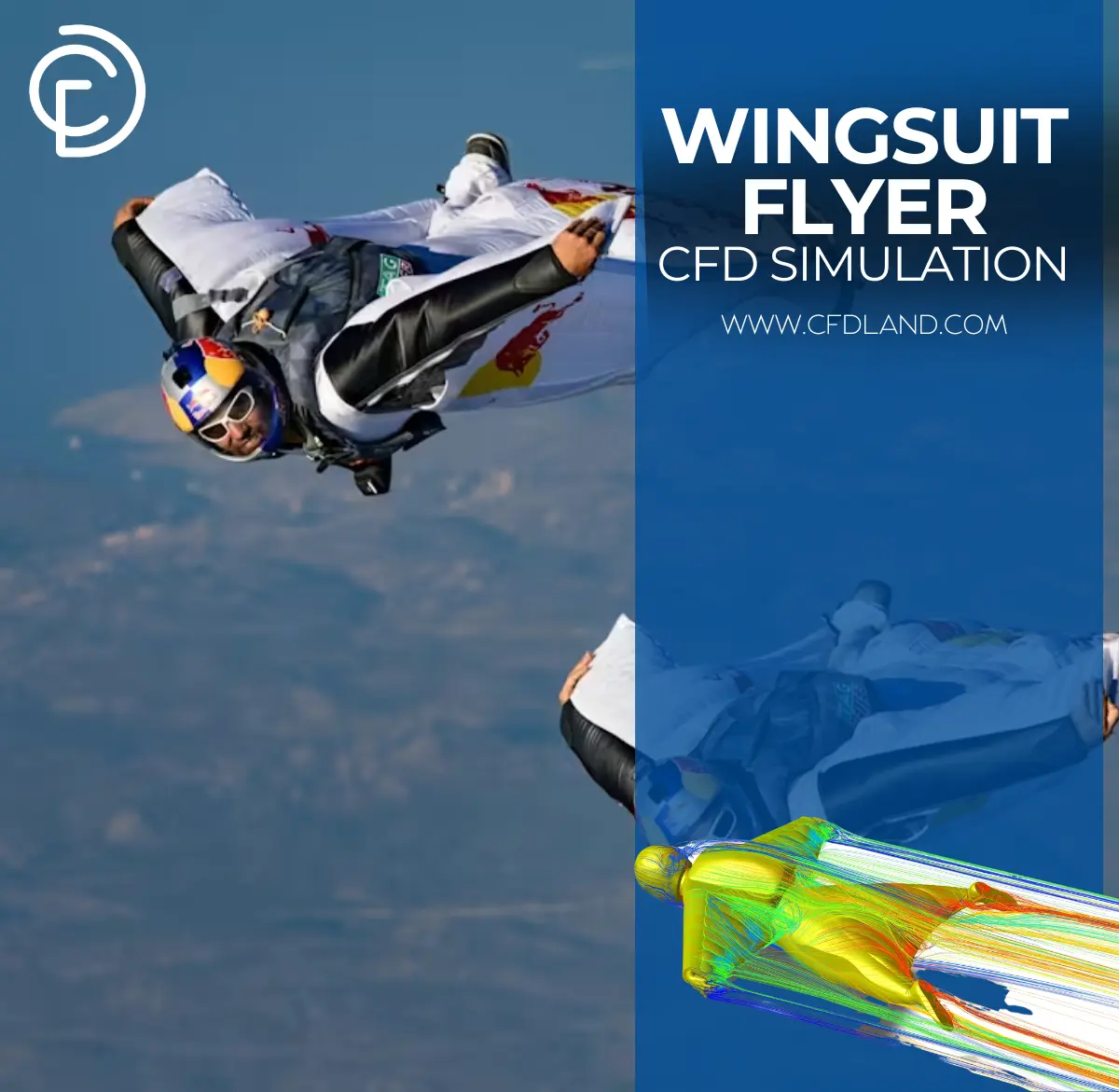
This tutorial shows you how to use wingsuit CFD simulation to see the amazing aerodynamics that make wingsuit flying possible! Wingsuit flight is all about the special way air flows around the human body in that cool bat-like suit. Our step-by-step guide helps you set up a complete wingsuit simulation in ANSYS Fluent to understand the science behind these extreme athletes. You’ll learn how to model air moving around a wingsuit flyer, see the lift and drag forces that keep them gliding, and discover the secret wingsuit physics that determines how far they can fly. This type of wingsuit aerodynamics analysis helps designers create better suits with improved glide ratios and safer flight performance. Using computational fluid dynamics for wingsuit design saves countless hours of dangerous real-world testing.
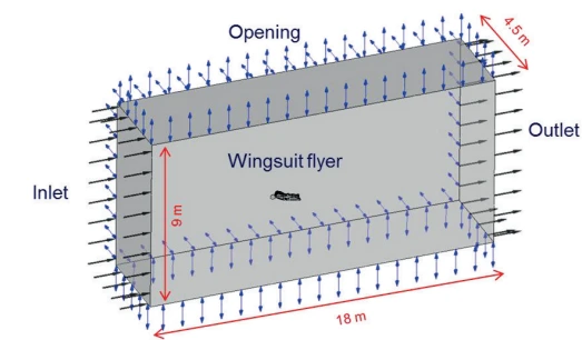
Figure 1: Boundary details and measurements of the computational domain in ANSYS
Simulation Process
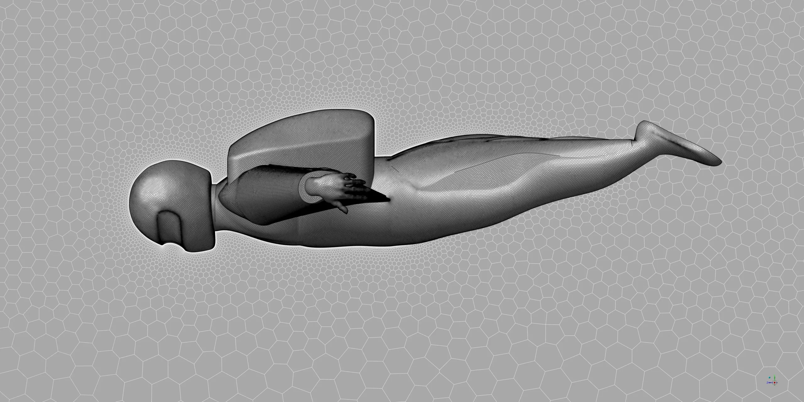
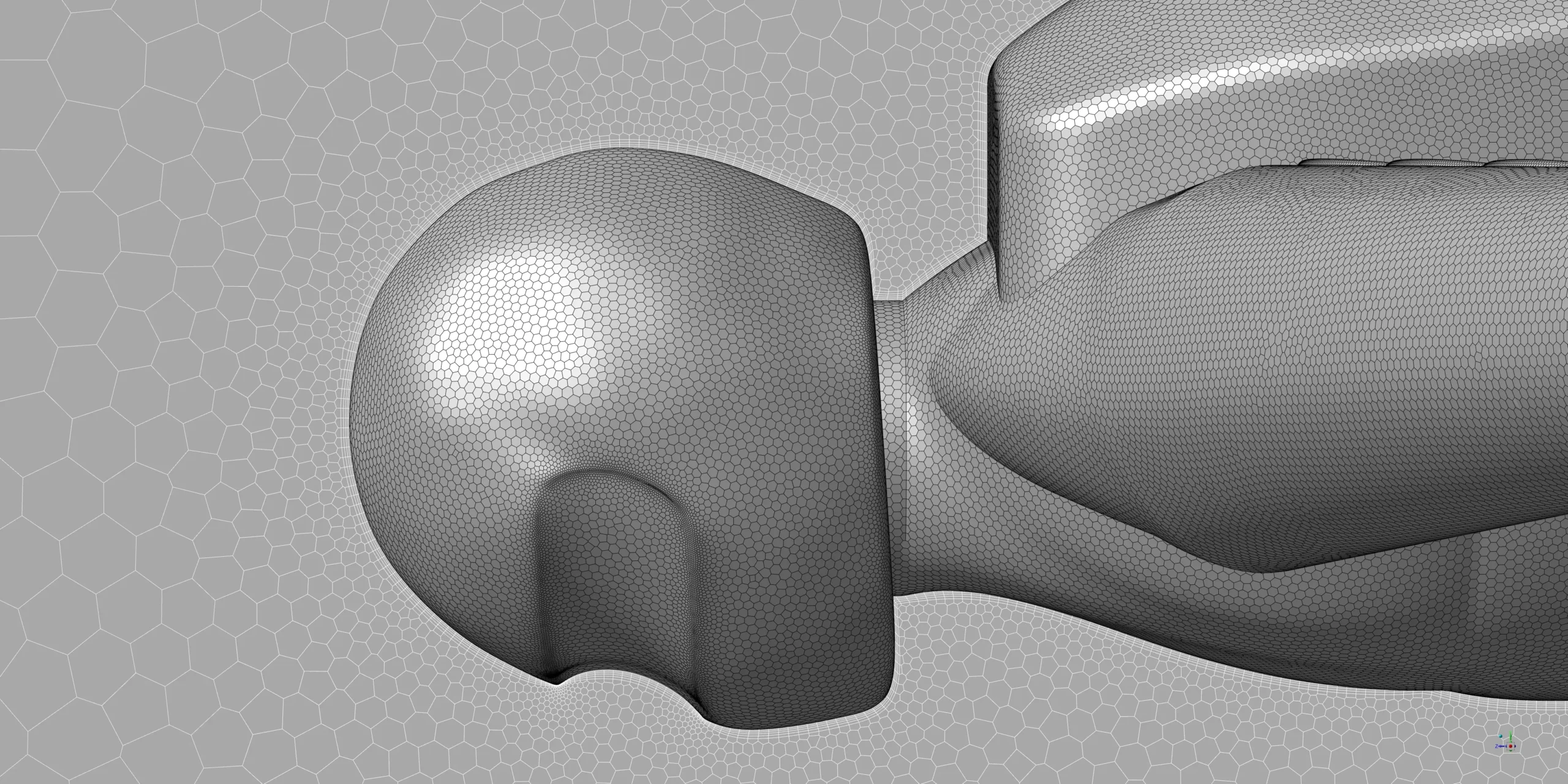
For our wingsuit simulation, we built a detailed 3D model that accurately represents a real flyer with arms and legs extended in the classic wingsuit position. We set the wingsuit at a 45° angle of attack (AOA), which represents a steep diving configuration that generates significant lift while maintaining forward speed. The computational domain was created large enough to capture all flow features without boundary interference. For meshing, we used polyhedra cells in ANSYS Fluent Meshing instead of standard tetrahedral elements because they give better accuracy with fewer cells – super important for capturing the complex flow around the human body shape.
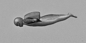
Figure 2: Polyhedra grid generated by Fluent Meshing for wingsuit flyer CFD Simulation
Post-processing
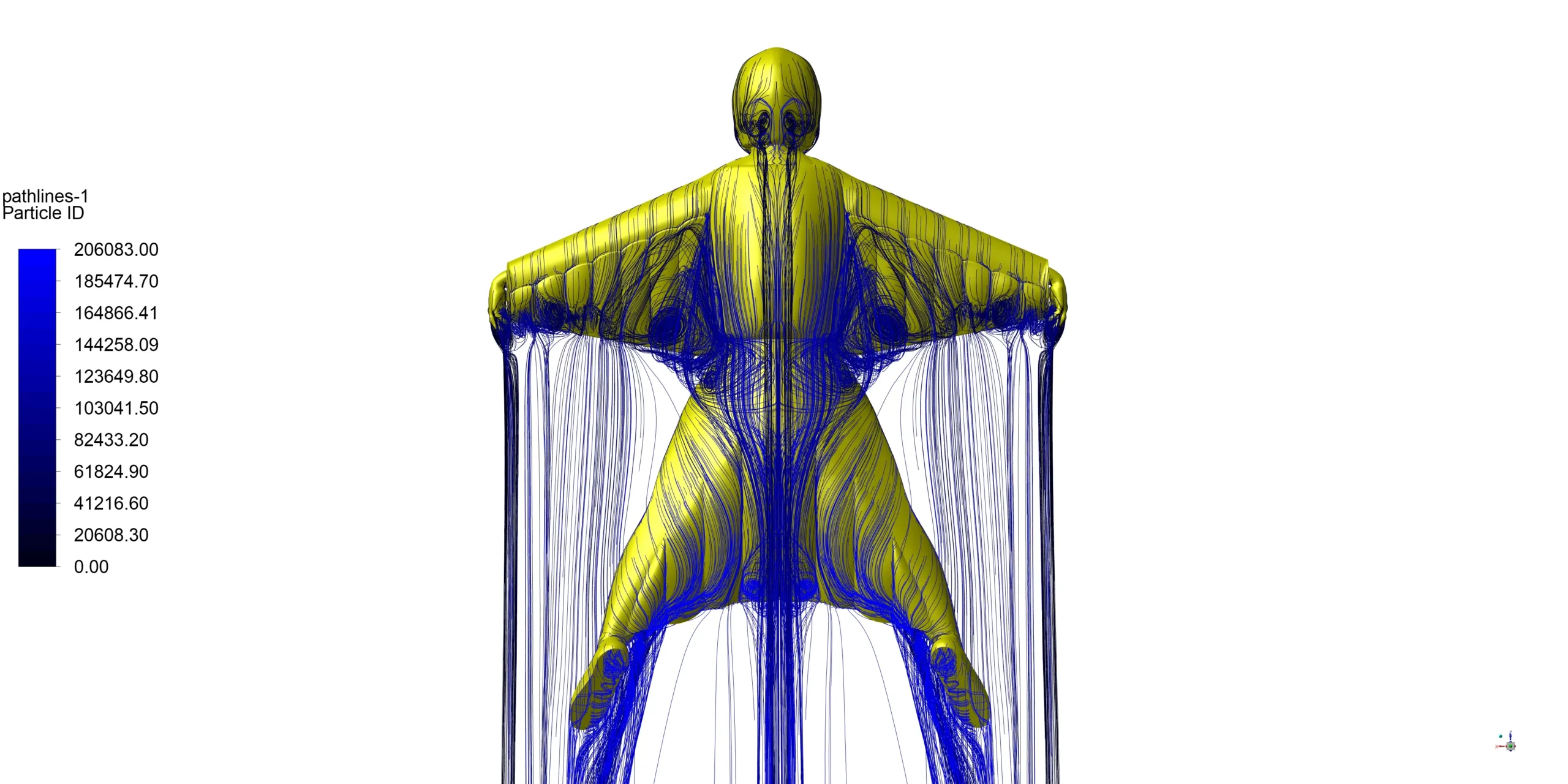
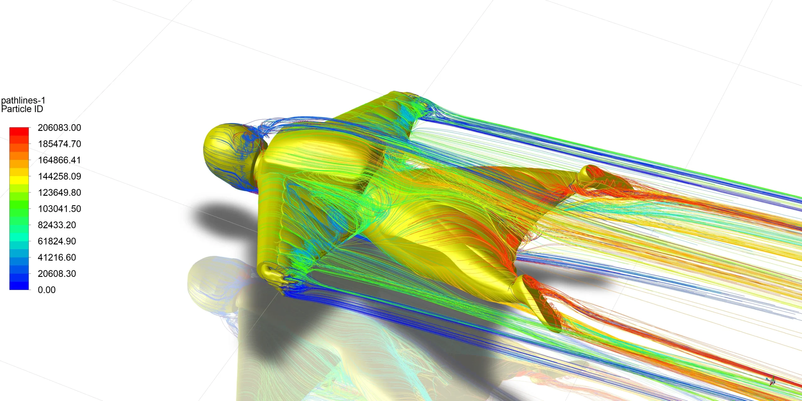
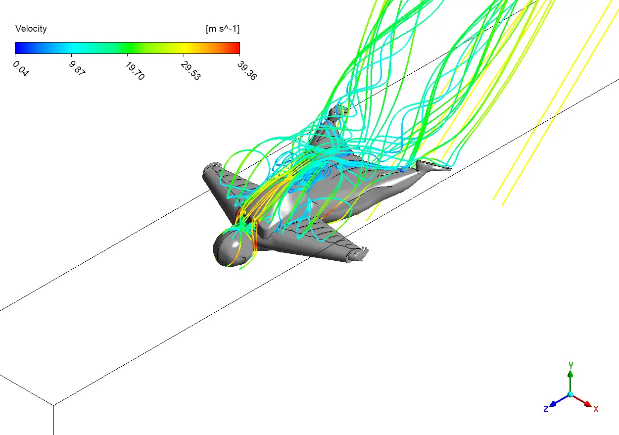
The streamlines depict fascinating airflow patterns around our wingsuit flyer that explain why these suits work so well. Notice the smooth, attached flow over the front of the body (yellow-green lines) where air accelerates to around 19 m/s, but then forms complex turbulent structures behind the flyer (blue swirls). The most interesting feature is how the wingsuit channels air between the arms and legs, creating the same effect as an aircraft wing. The simulation perfectly captures the highest velocities (yellow-orange) occurring at the leading edges of the arms where speeds reach nearly 30 m/s. From an engineering perspective, these results suggest that smoothing the transition between the arm and torso sections could reduce drag by minimizing the size of those blue wake regions. With measured drag at 994.86N and lift at 1137.92N, this gives us a lift-to-drag ratio of approximately 1.14 – typical for current wingsuit designs but suggesting room for improvement in future designs by modifying the arm geometry.
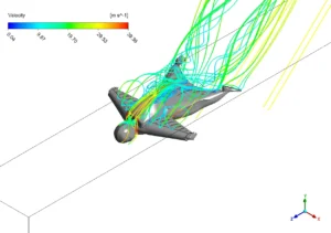
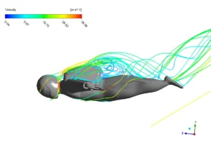
Figure 3: Velocity Streamlines Around Wingsuit
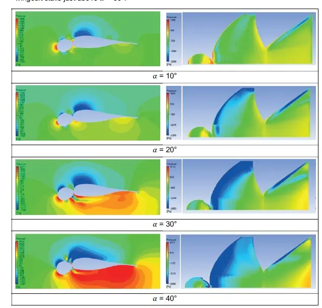
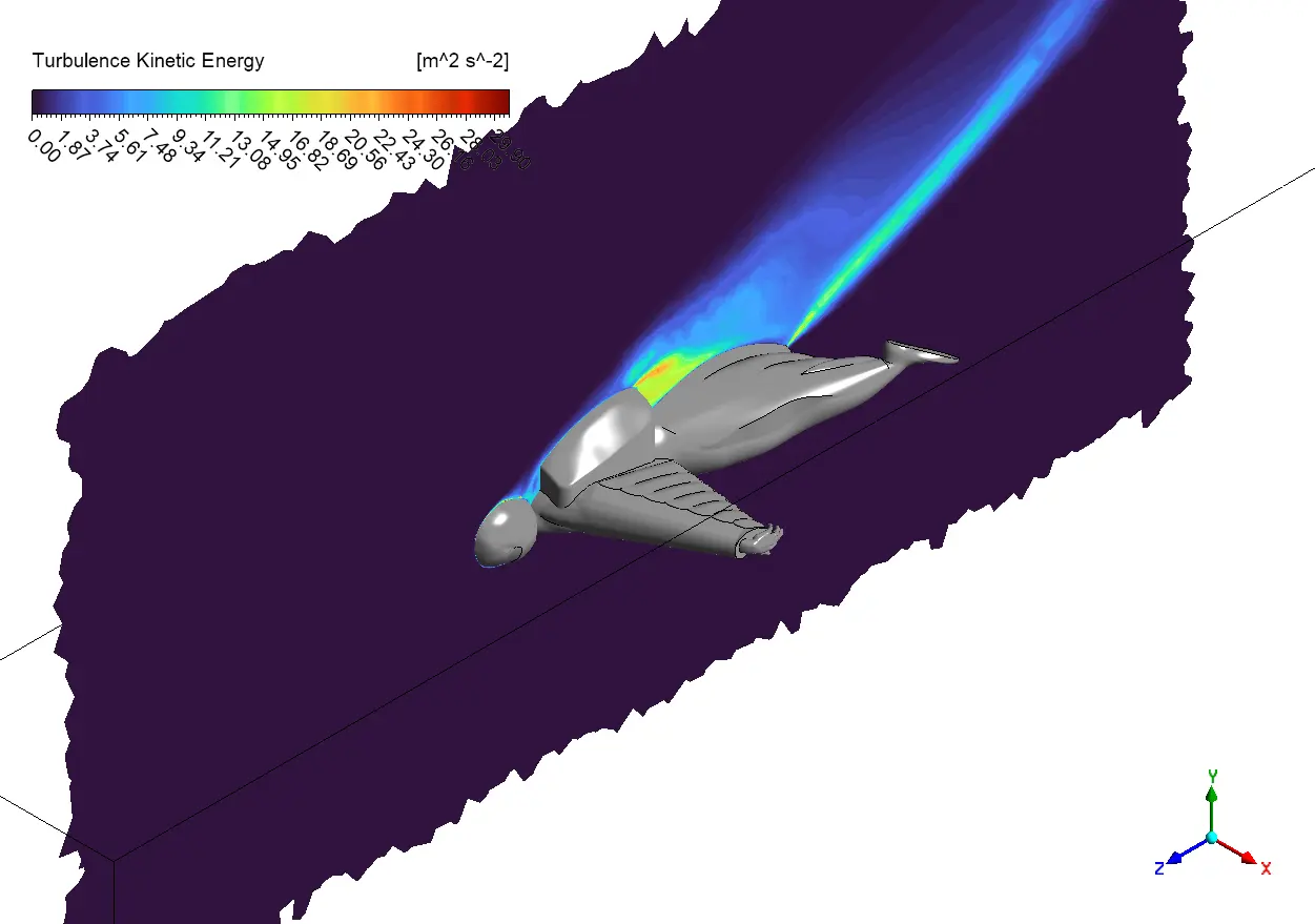
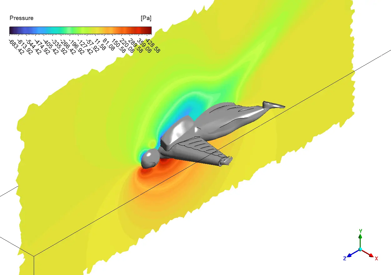
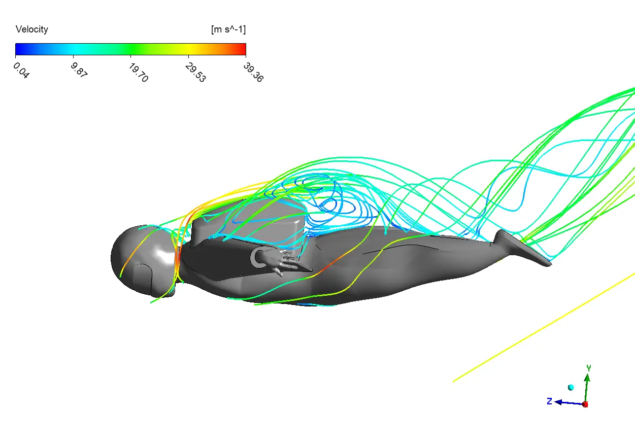
The second image shows a vertical slice through the flow field, revealing the dramatic pressure gradient created by the wingsuit body. The large orange-red region in front of the flyer indicates a high-pressure stagnation zone where air slows dramatically before diverting around the body. What’s particularly interesting is the green “acceleration zone” along the top surface of the wingsuit, showing exactly where lift generation occurs as air speeds up to about 15-18 m/s. The extensive blue-green wake behind the flyer extends much further than many would expect – nearly twice the body length – indicating significant energy loss that contributes to the 994.86N of drag. Looking at the third image from a side view, we can see how the flow separates from the back of the flyer’s head and creates a complex vortex structure (blue spiraling lines) that follows the body. This flow separation is unavoidable due to the blunt shape of the human form, but the simulation shows how the wingsuit design works to minimize these effects by streamlining the body as much as possible. For wingsuit designers, these results suggest focusing future improvements on the head-shoulder transition area where significant turbulence begins.
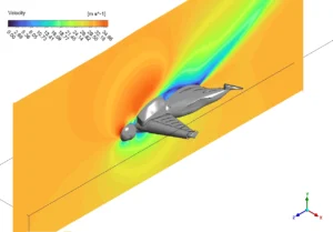
Figure 4: Velocity Contour in Vertical Slice


Reviews
There are no reviews yet.