


Dynamic Mesh in CFD
In computational fluid dynamics, many engineering problems involve moving parts or deforming geometries—like pistons in internal combustion engines, opening valves, or rotating blades—which cannot be accurately simulated with a fixed mesh. This is where the dynamic mesh method (also called moving meshes) becomes essential. The dynamic mesh in ANSYS Fluent allows the computational mesh to move, stretch, deform, or even regenerate based on boundary motion and interaction, making it ideal for time-dependent simulations. In a dynamic mesh CFD setup, mesh cells can change size, shape, and number throughout the solution process, offering a flexible and robust framework for simulating complex motions. While alternatives like the sliding mesh or Multiple Reference Frame (MRF) approach can simulate certain types of motion, they lack the adaptability required for problems involving large or irregular deformations. For these advanced scenarios, tools such as ANSYS moving mesh or ANSYS Fluent dynamic mesh UDFs provide unmatched control and precision. Overall, mastering dynamic mesh in ANSYS Fluent opens the door to simulating real-world motion with high accuracy.
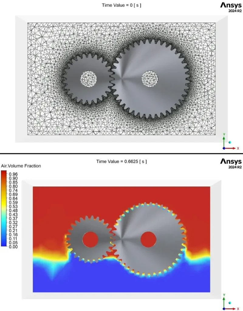
Figure 1- Gear Box Lubrication CFD Simulation Using Dynamic Mesh: ANSYS Fluent Dynamic Mesh Tutorial
Applications of Dynamic Mesh in CFD
All in all, dynamic mesh can be used wherever a domain boundary is moved. Here we will examine some of these issues.
Biomedical Simulations
Biomedical simulations use advanced computer modeling techniques to predict and analyze the behavior of biological systems. For example, biomedical CFD simulations can model blood flow in arteries, simulate joint movement, or evaluate the mechanical performance of prosthetic devices. Many of these applications involve moving boundaries or deforming geometries, where dynamic mesh CFD techniques—like those in ANSYS Fluent dynamic mesh simulations—are essential. The dynamic mesh method allows the mesh to adapt to time-dependent changes in shape or position, making it a powerful tool for accurately capturing the complex motions found in biomechanical systems.
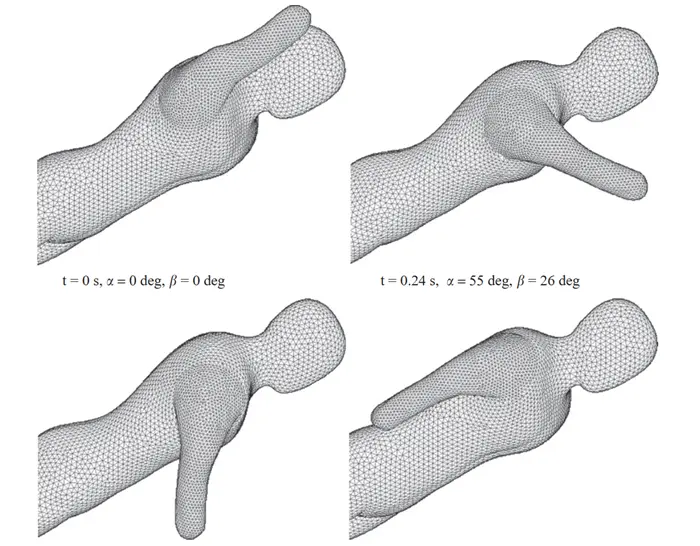
Figure 2- Dynamic mesh at different time to investigate a lower arm amputee swimmer’s performance
Structural Analysis
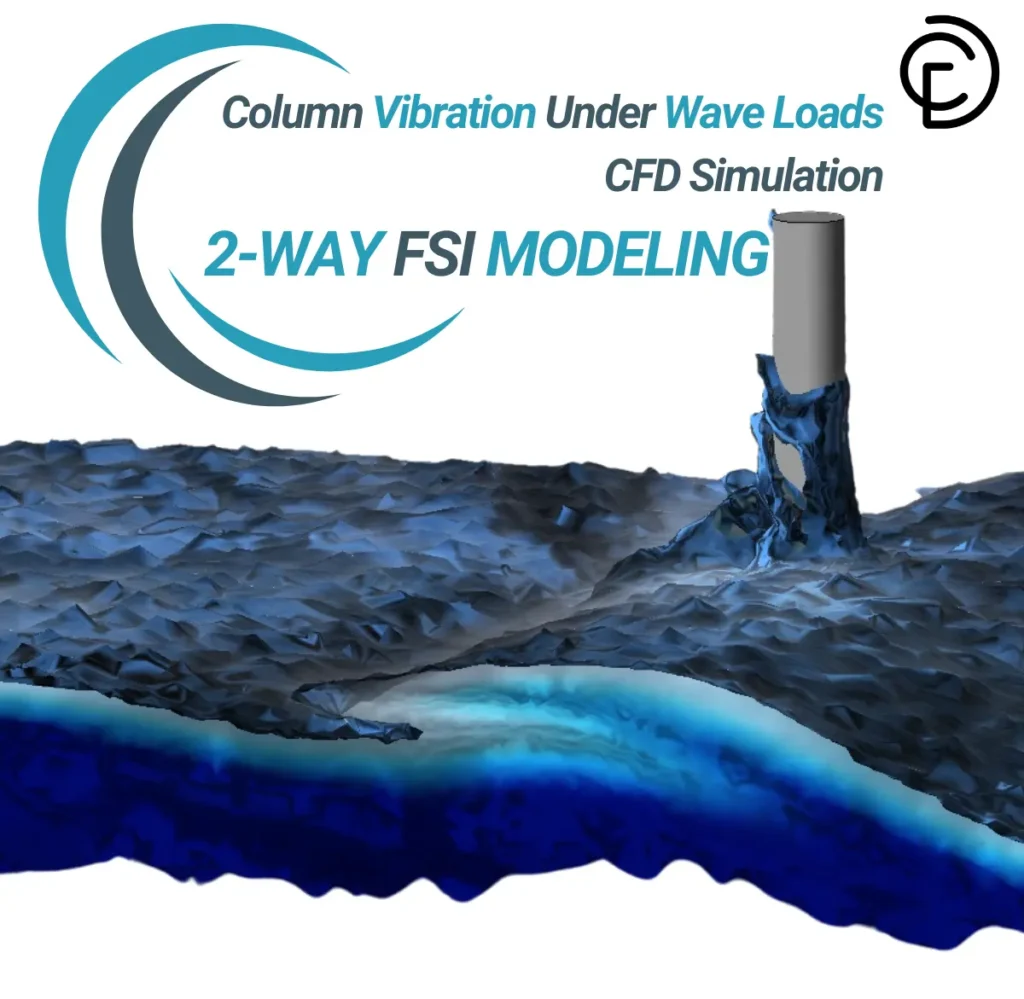
Fluid-Structure Interaction (FSI) problems involve the coupling between fluid flow and structural deformation, where the fluid exerts forces on a structure, causing it to deform, and this deformation, in turn, affects the fluid flow. Solving FSI problems requires continuous updating of the computational mesh to accurately capture the interaction between the fluid and the moving or deforming structure. This is where the ANSYS Fluent dynamic mesh 3D capability becomes essential. By using advanced dynamic mesh methods such as smoothing, layering, and remeshing, ANSYS Fluent ensures the mesh remains high-quality and accurately conforms to the structural changes. Fig.3 shows a Fluid-Structure Interaction with fully coupled mesh generation.
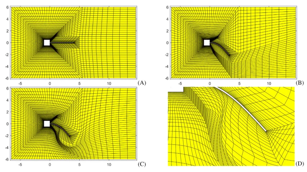
Figure 3- Flap: (A) initial mesh; (B) mesh after 1640 time steps for the coupled mesh generation approach; (C) mesh after 1640 time steps for the pseudo-solid approach; (D) zoom in on distorted elements of the pseudo-solid approach.
Turbomachinery and Rotating Equipment
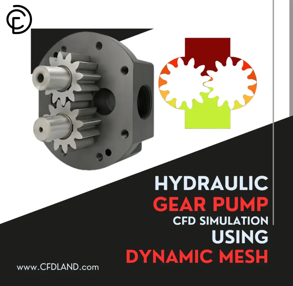
In turbomachinery like pumps, compressors, and turbines, rotating parts such as blades and impellers interact continuously with the fluid. To capture this motion, sliding mesh or dynamic mesh CFD methods are used. While sliding mesh handles steady rotation, dynamic mesh Fluent is essential for unsteady or deforming motions. These approaches help simulate real-time blade-fluid interaction, improving design accuracy and performance prediction. Tools like ANSYS Fluent dynamic mesh tutorial make implementing these methods more accessible .For example, the Pelton wheel (Fig.4), a vital component in hydroelectric power generation, is an advanced impulse turbine design that necessitates complex computer analysis to achieve peak performance. Engineers can now correctly model the fluid-structure interactions within these turbine systems using ANSYS Fluent’s Six Degrees of Freedom (6DOF) Dynamic Mesh CFD modeling technology.
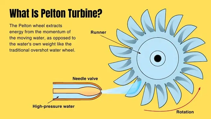
Figure 4- The Pelton wheel or Pelton Turbine is an impulse-type water turbine: A Dynamic Mesh CFD Simulation Example
Automotive Engineering
In automotive engineering, dynamic mesh CFD is essential for accurately simulating internal combustion engines, where the piston moves inside the cylinder and the chamber volume changes constantly. By using the dynamic mesh method in tools like ANSYS Fluent, engineers can model the motion of the piston and changing geometry in real time, allowing precise analysis of airflow, fuel-air mixing, and combustion efficiency throughout the engine cycle. This approach helps optimize engine design, improve performance, and reduce emissions without the need for costly physical prototypes.
Figure 5- Dynamic mesh and update nodes under equal step size for a piston-cylinder system
Aerodynamic Applications
Another important application area of dynamic mesh CFD simulation is in aerodynamic and aerospace engineering, particularly for simulating airfoils and aircraft wings. These simulations help analyze how the wing or airfoil deforms or moves under aerodynamic forces, especially in cases involving flapping wings, morphing structures, or control surface motions like ailerons or elevators. Using ANSYS Fluent dynamic mesh in these cases ensures accurate modeling of the interaction between the moving surfaces and the airflow.
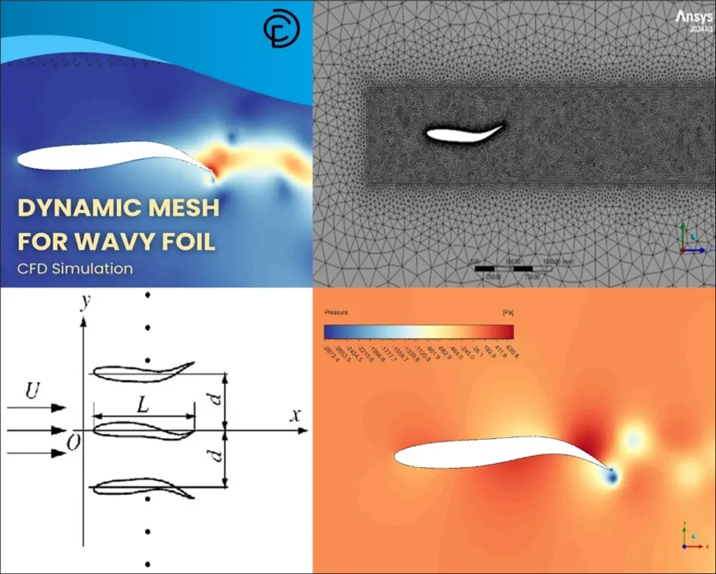
Figure 6- Dynamic Mesh for Wavy Foil CFD Simulation, A CFDLAND Dynamic Mesh Tutorial
Dynamic Mesh Methods in ANSYS Fluent
The Fig.7 shows the Dynamic Mesh settings panel in ANSYS Fluent, where users can activate and configure dynamic mesh methods for CFD simulations. The interface displays three key mesh methods—Smoothing, Layering, and Remeshing—each allowing for advanced mesh adaptation around moving boundaries. The checkboxes indicate which methods are enabled, and additional options such as In-Cylinder and Six DOF (Degrees of Freedom) are available for more complex motions. The left panel highlights the simulation setup tree, with Dynamic Mesh selected, demonstrating how users integrate dynamic mesh features into their CFD workflow in ANSYS Fluent.
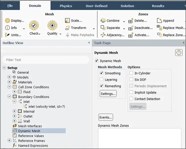
Figure 7- Schematic of Dynamic Mesh Setup in ANSYS Fluent
Dynamic Mesh Options in ANSYS Fluent (Fig.7)
The Dynamic Mesh options in ANSYS Fluent provide advanced controls to simulate moving and deforming geometries in CFD analysis. These options are essential for achieving accurate and efficient dynamic mesh simulation across various engineering applications.
In-Cylinder Model
The In-Cylinder dynamic mesh model is specifically designed for transient CFD simulations, such as modeling fluid flow and combustion inside the cylinder of an internal combustion engine. As the piston moves, the simulation domain automatically adapts, making this model ideal for analyzing automotive engines and other cylindrical devices where geometry changes with time.
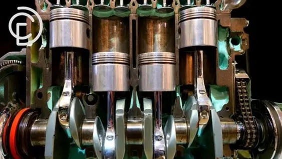
Figure 8- In-cylinder dynamic mesh is used to simulate combustion inside the cylinder of an internal combustion engine car. As the piston moves, the simulation domain changes.
Six Degree of Freedom (Six DOF)
The Six DOF model in ANSYS Fluent calculates real-time forces and moments acting on moving rigid bodies, using pressure and shear data from fluid flow. It solves for both translation and rotation along all three Cartesian axes, making it perfect for simulating components that move and rotate freely. Users can also restrict movement to certain axes as required.

Figure 9- Box Falling Using 6 DOF Dynamic Mesh CFD Simulation, A CFDLAND Dynamic Mesh Tutorial
Implicit Update
The Implicit Update option updates the mesh at every time step, making it suitable for simulations where mesh motion depends on fluid-structure interaction (FSI). This ensures the mesh always fits the evolving geometry, critical for accurate CFD dynamic mesh results.
Contact Detection
With Contact Detection in dynamic mesh ANSYS, the software identifies when two or more moving or stationary geometries come into contact. This feature maintains mesh quality and prevents errors during complex interactions, such as in multi-body or assembly simulations
Ansys Fluent Dynamic Mesh Modeling
When performing dynamic mesh simulation in ANSYS Fluent, several mesh methods are available to update the mesh as the geometry changes during the analysis. These dynamic mesh methods are essential for maintaining accuracy and stability in simulations involving moving boundaries. In deforming regions subject to the boundary motion, three approaches are available for updating the volume mesh: smoothing, dynamic layering, as well as local remeshing.
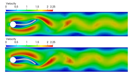
Figure 10- Dynamic Mesh CFD Simulation Example: Mesh moving techniques in fluid-structure interaction:
Smoothing
The smoothing dynamic mesh method keeps the number of cells and their connectivity unchanged. This approach includes several techniques, such as spring/Laplace/boundary layer, diffusion, linearly elastic solid, and radial basis function methods. Smoothing dynamic mesh is effective when boundary movement is small, ensuring mesh quality without altering the original mesh structure.
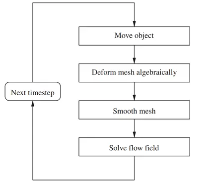
Figure 11- Coupling of dynamic mesh smoothing scheme with flow solver
During the smoothing process all boundary nodes were restricted to move along the border edges. Fig. 12 shows the initial mesh including the results from the first and third iterations.
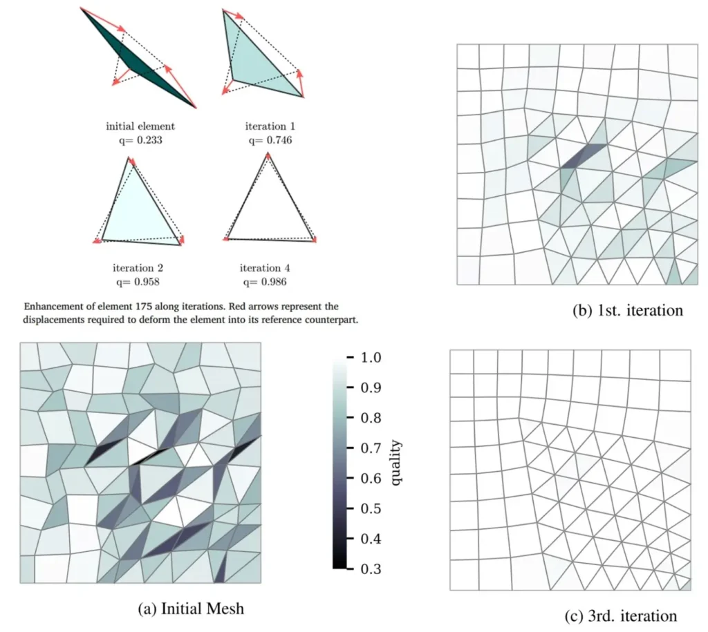
Figure 12- Dynamic Mesh Methods in ANSYS Fluent: Mesh Smoothing Results
Layering
For prismatic meshes like wedge or tetrahedral grids, layering is used to add or remove layers of cells near the moving boundary. This dynamic mesh ANSYS technique is especially useful in simulations with piston or valve motion, as it helps maintain mesh quality and accurate results. As shown in the Fig.12, the dynamic layering method can increase or decrease layers of cells next to a moving boundary, and can simulate the translation movement of the pipe while tripping. The cells of layer j are merged or split with cells of the next layer i depending on the cells height of layer j.
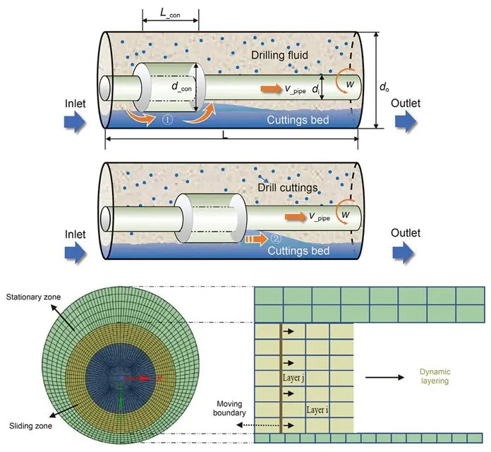
Figure 13- Schematic Illustration of the Dynamic Mesh Layering
Remeshing
When the boundary movement is too large for the existing mesh, cell quality can deteriorate, leading to calculation errors and convergence issues. Remeshing allows ANSYS Fluent to identify problematic cells and regenerate them automatically. It is recommended to use the unified remeshing method, which helps preserve the original mesh distribution and reduces computational cost. By leveraging dynamic mesh Fluent CFD capabilities like remeshing, users can ensure reliable and efficient simulations even with significant geometry changes.
For finding more detail about how applying Remeshing in ANSYS Fluent, we employed 6-DOF Dynamic mesh model to follow the savonius turbine performance from its starting point until it reaches working condition (Fig.14). The transient simulation regenerate the grid over time adopting Smoothing and Remeshing techniques.
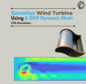
Figure 14- Savonius Wind Turbine Using 6DOF Dynamic Mesh CFD Simulation: ANSYS Fluent Dynamic Mesh Tutorial
ANSYS Dynamic Mesh UDF
ANSYS Fluent Dynamic Mesh UDFs (User-Defined Functions) provide the flexibility to customize how the mesh adapts to moving or deforming boundaries during CFD simulations. The dynamic mesh UDF allows users to control the movement of mesh nodes programmatically at each time step—ideal for complex, transient simulations like piston motion in internal combustion engines or bio-inspired movements.
If you want to understand how UDF can be applied for CFD dynamic mesh, you can refer to “Erosive Burning Using Dynamic Mesh & UDF CFD Simulation, ANSYS Fluent Tutorial” (Fig.15). In solid fuel combustion systems, erosive burning is a complicated process that speeds up the burning process when fast-moving gas flows across the fuel surface. In this tutorial, the grid will be re-meshed by dynamic mesh module techniques including Smoothing and Remeshing methods as the motor wall starts deforming. Additionally, in this comprehensive dynamic mesh tutorial, User-Defined Functions (UDFs) are also very important for describing the physics of erosive burning because they let you make your own mathematical models of the burning rate, heat transfer, and surface regression.

Figure 15- Erosive Burning Using Dynamic Mesh & UDF CFD Simulation, ANSYS Fluent Dynamic Mesh Tutorial
The flowchart illustrates (Fig.16) the typical logic of an ANSYS dynamic mesh UDF (User-Defined Function) used in CFD simulations with moving boundaries. At each time step, the UDF loops over surface nodes, checks if each node has been updated, and determines if the node is within the morphing (deforming) region of the mesh. If so, the node position is recalculated using a parametric method to accurately capture dynamic motion, such as piston movement or complex boundary deformation. This structured approach ensures that mesh quality is maintained and boundary motion is precisely modeled, making it an essential part of advanced dynamic mesh simulation in ANSYS Fluent for applications like internal combustion engine analysis and fluid-structure interaction.
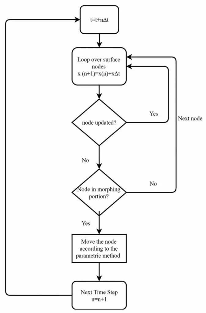
Figure 16- Algorithm used in the UDF to drive dynamic meshing in Fluent
Dynamic Mesh Modeling in ANSYS Fluent – CFDLAND Services
At CFD LAND, we specialize in dynamic mesh simulations using ANSYS Fluent. These simulations handle moving or deforming geometries, ideal for modeling complex motions like valves, flaps, falling objects, and fluid–structure interaction (FSI). Dynamic mesh setup requires deep expertise in UDF coding, mesh motion methods, and Six DOF modeling. Our team has completed dozens of successful projects across industries and offers high-quality CFD solutions tailored to your needs.
CFDLAND Dynamic Mesh CFD Applications
- Six DOF motion for ships, boats, and tidal turbines
- Valve and wing flap motion
- Releasing objects (e.g., food boxes, packages)
- Underwater vehicle movement
- Solid fuel combustion modeling
- Blood flow and heart FSI simulation
- Internal combustion engine simulation
Overall, learning dynamic mesh is very time-consuming and requires a lot of experience and trial and error. Don’t worry, we are here to help you. Order ANSYS Fluent CFD simulation from us. Be sure of the quality of our work.