

Sloshing, the dynamic movement of liquid inside partially filled containers, is one of the most difficult multiphase flow phenomena in engineering applications. This free-surface flow characteristic happens in a variety of locations including fuel tanks in vehicles and spacecraft, large-scale liquid storage facilities, and LNG tankers settling severe seas. Accurate modeling of sloshing forces is critical for structural design since these oscillations have a major impact on system stability and structural integrity. In this complete course, we’ll look at how to successfully describe 3D sloshing behavior with ANSYS Fluent’s dynamic mesh features, resulting in a more realistic simulation than static approaches. This advanced tutorial expands on our earlier 2D sloshing simulation (available at CFDLand’s 2D Sloshing Tank Tutorial), extending the analysis to three dimensions for a more accurate representation of complicated sloshing patterns seen in real-world scenarios. Plus, this study features from the valuable reference paper entitled “Study on the Effect of Density Ratio of Liquid and Gas in Sloshing Experiment”.
- Reference [1]: Yangjun, Ahn, et al. “Study on the Effect of Density Ratio of Liquid and Gas in Sloshing Experiment.” The 26th International Workshop on Water Waves and Floating Bodies, Copenhagen, Denmark. 2012.
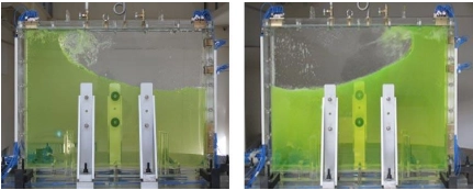
Figure 1: experimental sloshing test [1]
Simulation process
The computational domain for this 3D sloshing tank simulation uses a highly refined structured grid with 7,145,952 cells—a resolution needed to correctly represent the complicated free-surface behavior despite the high computing cost. To accurately follow the water-air interface dynamics during sloshing, we conducted a transient analysis using ANSYS Fluent’s Volume of Fluid (VOF) multiphase model. The simulation uses Fluent’s dynamic mesh capabilities, which are controlled by a custom User-Defined Function (UDF) that mathematically describes the oscillatory motion applied to the tank geometry. For quantitative analysis, two pressure sensors were strategically placed on the tank’s top face to monitor temporal pressure variations caused by liquid impact during sloshing events.
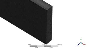
Figure 2: Fully structured grid over sloshing tank CFD study
Post-processing
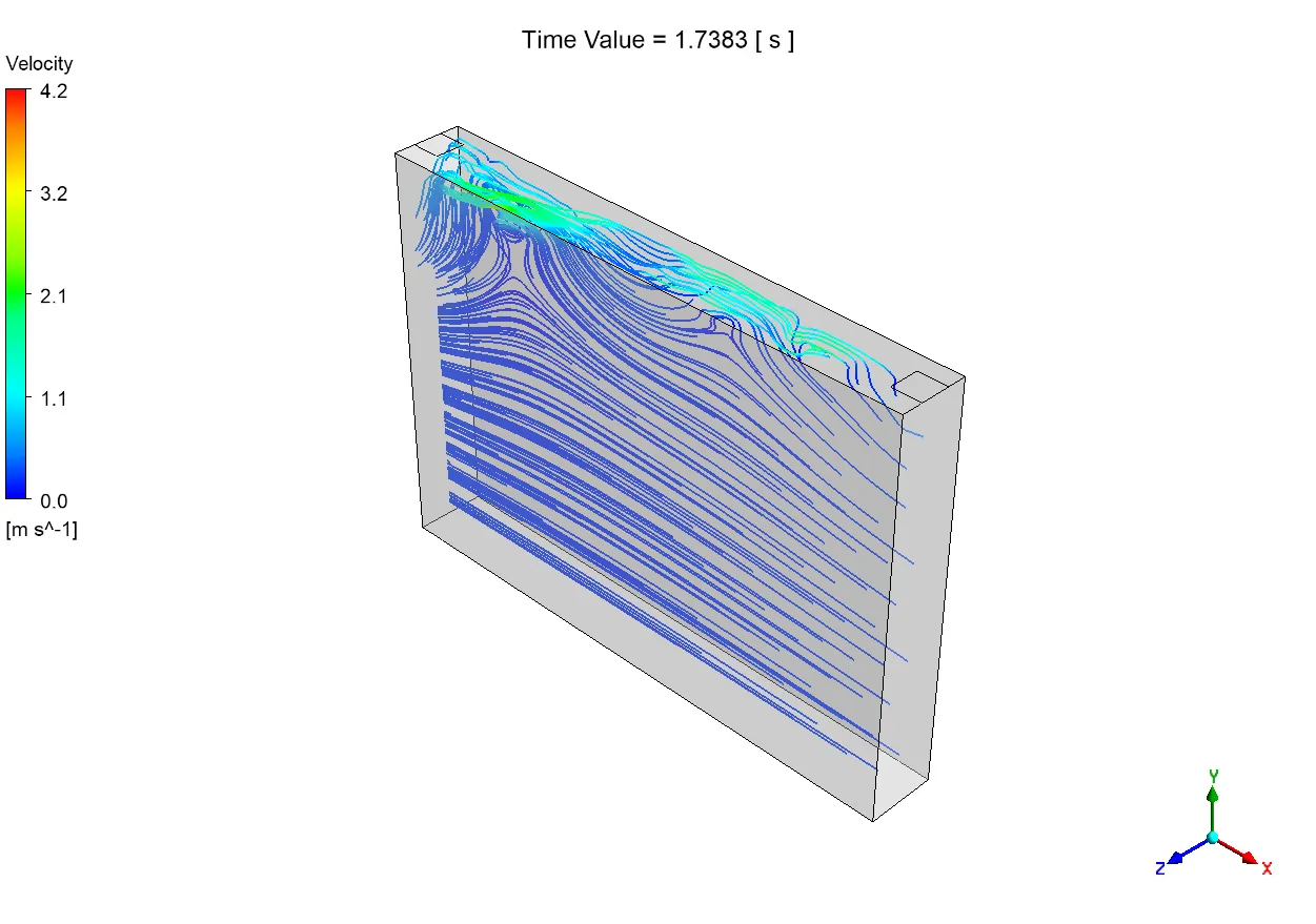
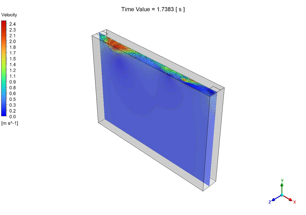
At 1.7383 seconds, the velocity streamline image shows complicated three-dimensional flow patterns that are typical of more advanced sloshing behavior. Near the free surface, speeds reach their highest point at 4.2 m/s (shown by the green-yellow areas), which are mostly joined together in the upper left corner, which is where waves break. The uneven speed distribution is caused by the resonance between the tank’s oscillation frequency and the liquid’s natural swirling frequency, which makes the wave motion stronger. The high-resolution mesh accurately depicts important flow features, such as the formation of boundary layers along tank walls, the formation of vortices at wave crests, and the complicated interactions between the water and air phases.
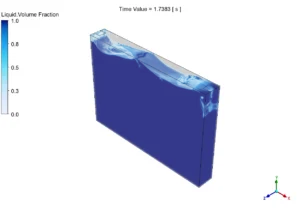
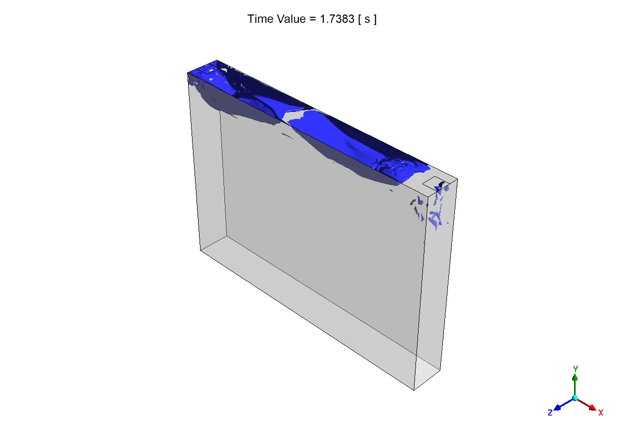
Figure 3: Liquid volume fraction clearly shows water sloshing inside the tank
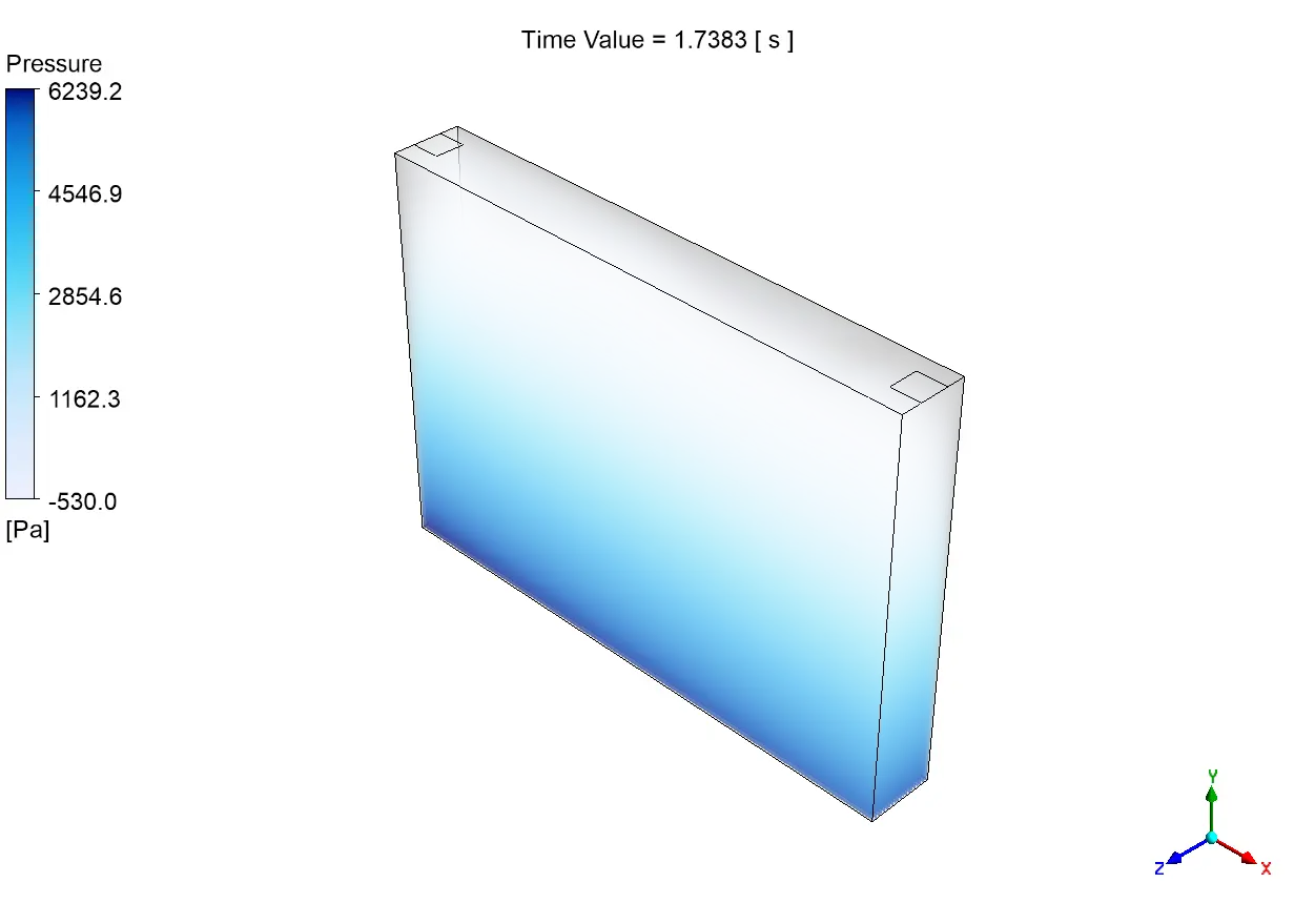
The data from the pressure sensors gives us important information about sloshing impact loads. For example, Sensor 1 (top left) recorded a maximum dynamic pressure spike of about 2000 Pa, which happened at the same time as a straight wave hitting the upper left corner. Sensor 2 (top right) records its highest pressure of about 1700 Pa a lot later. This shows that sloshing impacts are uneven and phase-shifted in three directions. This difference in time between the highest pressures at two different corners proves that rotating wave modes and diagonal sloshing patterns are present, which are typical of rectangular tanks moving in complex ways. The big difference between dynamic and static pressure readings (up to 2000 Pa) shows how resonant sloshing can have a big amplifying effect. This is important information for structural engineers who are making containers for transportation uses where fatigue failure from cyclical pressure loading is still a big problem.
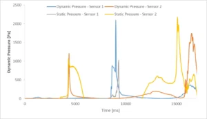
Figure 4: Pressure sensors implemented on tank top surface to measure pressure amplitude during sloshing


Reviews
There are no reviews yet.