


An Axial Fan With Perforated Blade Fluent simulation is a computer model of a new type of fan designed to be very quiet. This Perforated Blade CFD analysis is important for Quiet Fan Design. Like a normal fan, it has blades that spin to move air. But these special blades have small holes, or perforations, on them. A Perforated Blade Fluent simulation shows how these holes change the airflow to reduce noise and improve how the fan works. This study uses the methods from the key reference paper by Yadegari et al. [1] to make sure our model is accurate and reliable.
- Reference [1]: Yadegari, Mehdi, et al. “Reducing the aerodynamic noise of the axial flow fan with perforated surface.” Applied Acoustics215 (2023): 109720.
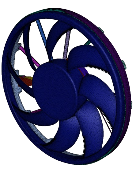
Figure 1: A schematic of the 3D geometry used for the Axial Fan With Perforated Blade CFD simulation.
Simulation Process: Fluent MRF Setup, Modeling Steady-State Flow for a Perforated Fan
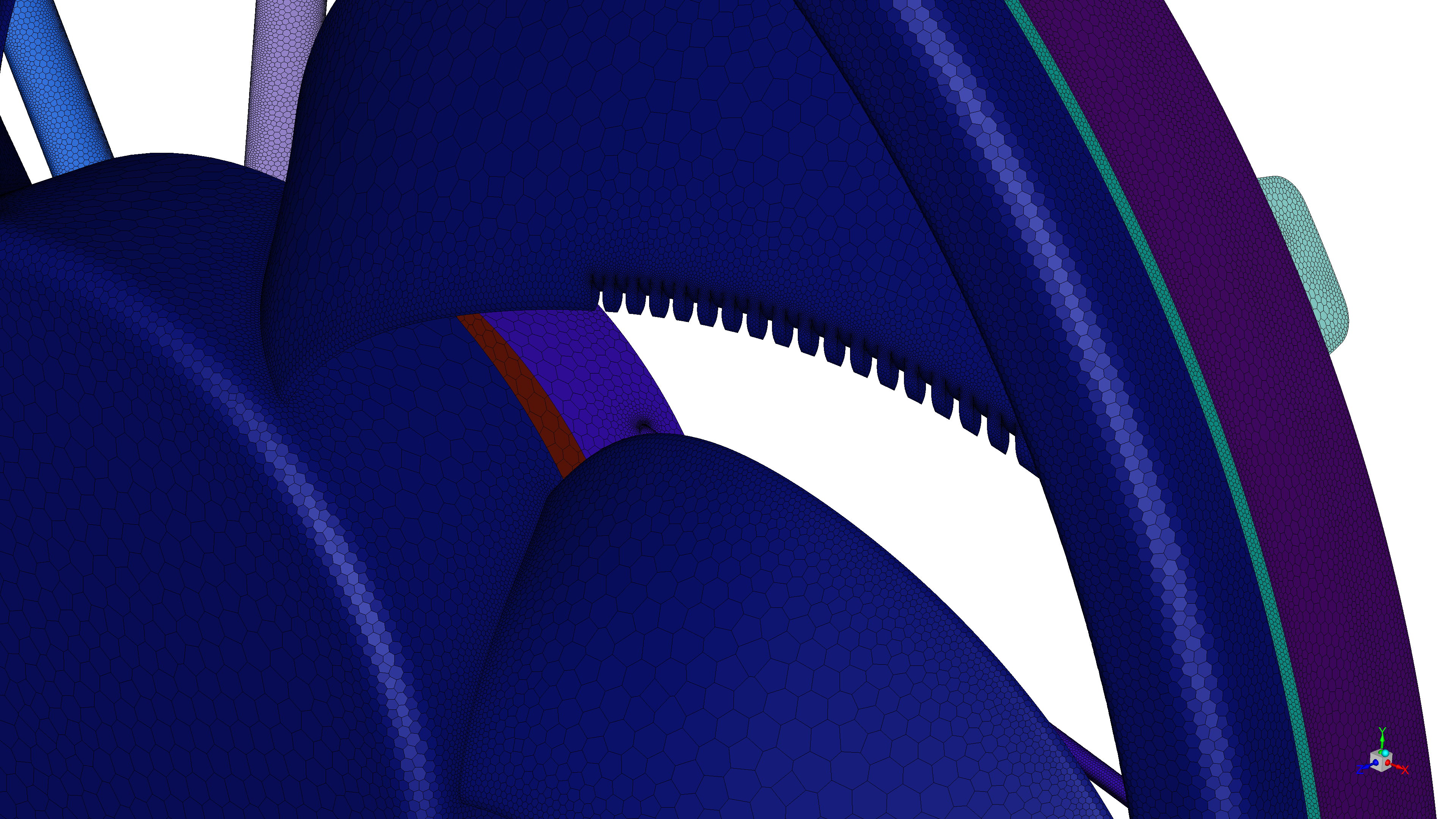
To perform this Axial Fan CFD study, we first built the 3D geometry. This geometry had two main parts: a smaller, rotating cylinder zone that contained only the fan rotor, and a larger, stationary zone for the air around the fan and its housing. We then created a high-quality hybrid mesh using 10,132,179 polyhedral and hexahedral cells to accurately capture the flow around the complex blade shapes. In ANSYS Fluent, we used the Multiple Reference Frames (MRF) model. The MRF method is a steady-state approach that is excellent for Turbomachinery CFD Fluent problems because it calculates the flow in the spinning zone and the stationary zone separately and connects them, which is much faster than a full transient simulation. The fan’s rotational speed was set to 2818 rpm. To correctly model the turbulent airflow, we used the SST k-ω turbulence model, which is very good at predicting flow close to walls like the fan blades.
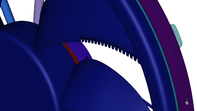

Figure 2: The high-quality hybrid mesh with 10,132,179 polyhedral and hexahedral cells used for the MRF Simulation Fluent analysis.
Post-processing: CFD Analysis, How Perforations Improve Pressure and Stability
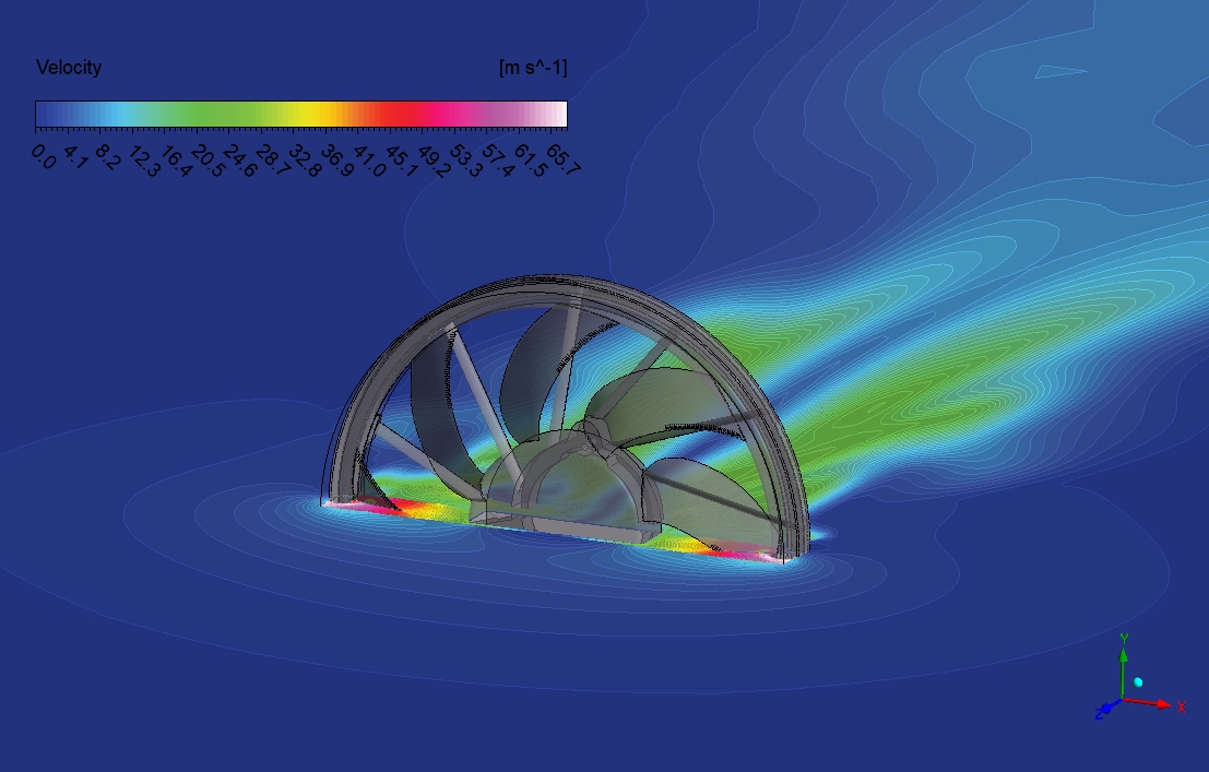
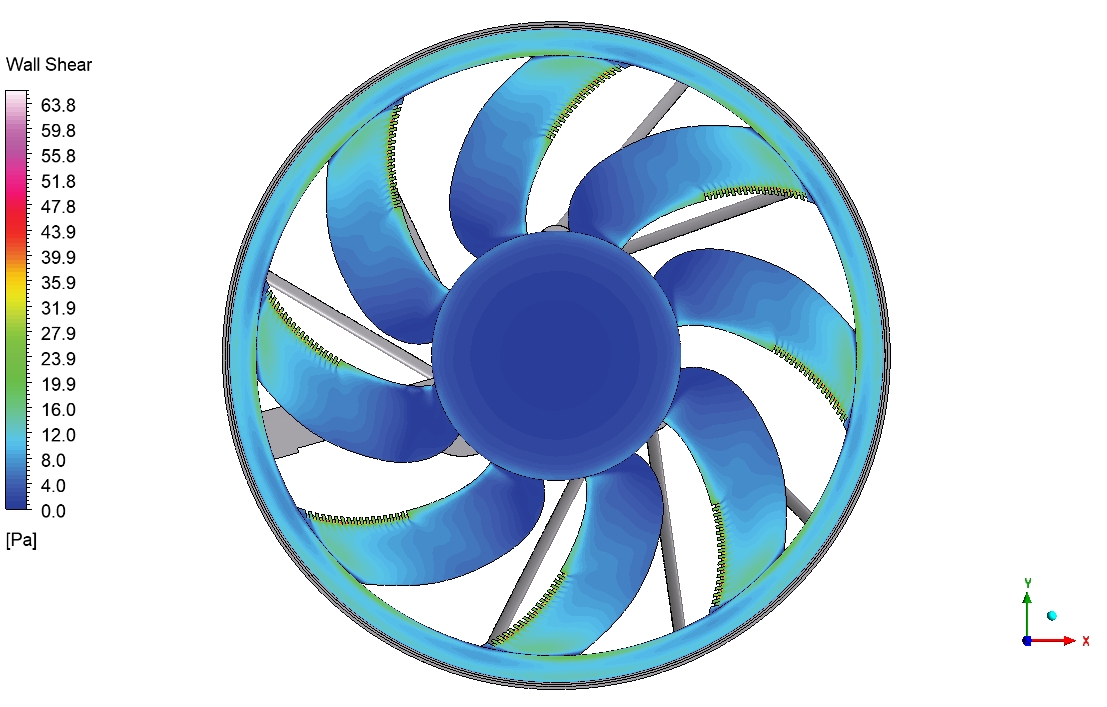
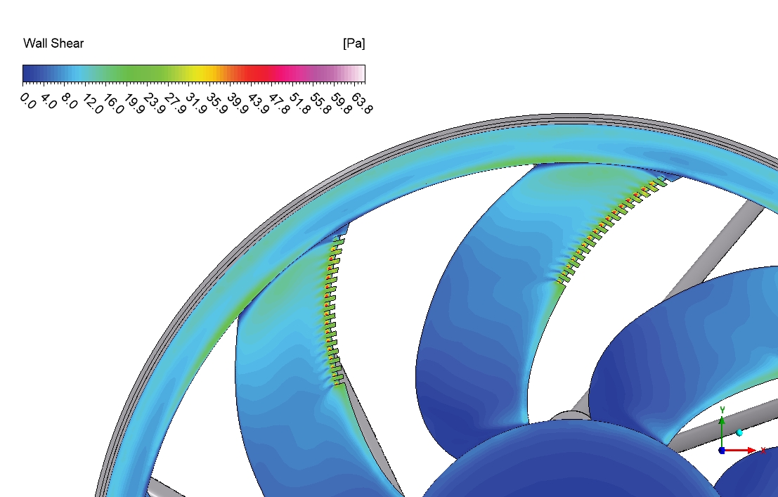
The pressure contour is a diagnostic map that tells the story of how the fan is working. From an engineering standpoint, it clearly shows the fan creating a pressure difference, which is how it pushes air. The key result is the smooth pressure gradient across the fan blades. The colors change gently, without sharp, sudden shifts. This is a very important finding. In fan design, sharp pressure changes create turbulence, and turbulence creates noise. The smooth change here suggests that the perforations are successfully breaking up the air swirls, leading to a quieter operation. The design is doing exactly what it was meant to do: reducing the pressure differences that are a major source of aerodynamic noise.
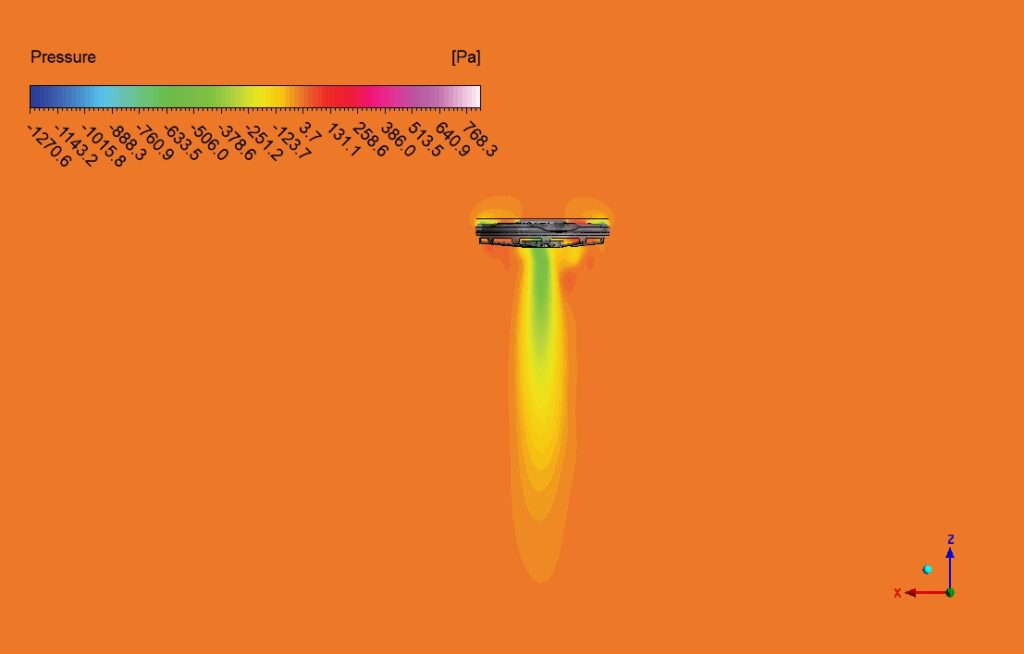
Figure 3: A contour of static pressure from the Pressure Distribution CFD analysis, showing the pressure gradient across the fan blades.
This analysis also confirms the fan’s overall performance. The large, concentrated low-pressure zone in the wake region behind the fan shows that momentum is being effectively transferred to the air, which means the fan is creating thrust efficiently. Furthermore, the pressure distribution is very symmetrical across the fan’s face. This balance is critical for the fan’s mechanical health. It means the load on the blades is even, which leads to less vibration and a longer operational life for the fan’s components. The most important achievement of this simulation is its ability to visually prove the design concept: it directly connects the physical feature (the perforations) to the desired engineering outcome (a smoother pressure profile), providing clear evidence that this design will be quieter and more stable than a standard solid blade fan.


Reviews
There are no reviews yet.