

Air purifiers are very important machines for our homes and offices. They clean the air we breathe. An Air Purifier Fan CFD simulation helps engineers design better ones. The fan inside the purifier has a very hard job. It must pull dirty air from the room and then push that air through thick filters. These filters, like HEPA filters, are what catch harmful things like dust and pollen. But they also block the air, like a dam blocking water. If the fan is not strong enough, not enough air will get cleaned. If the fan is too strong, it can be noisy and waste energy. This report uses Filtration CFD with ANSYS Fluent to study this difficult balance. We look at the airflow inside the purifier to see how the fan and filters work together. This helps us build machines that give us the cleanest possible air.
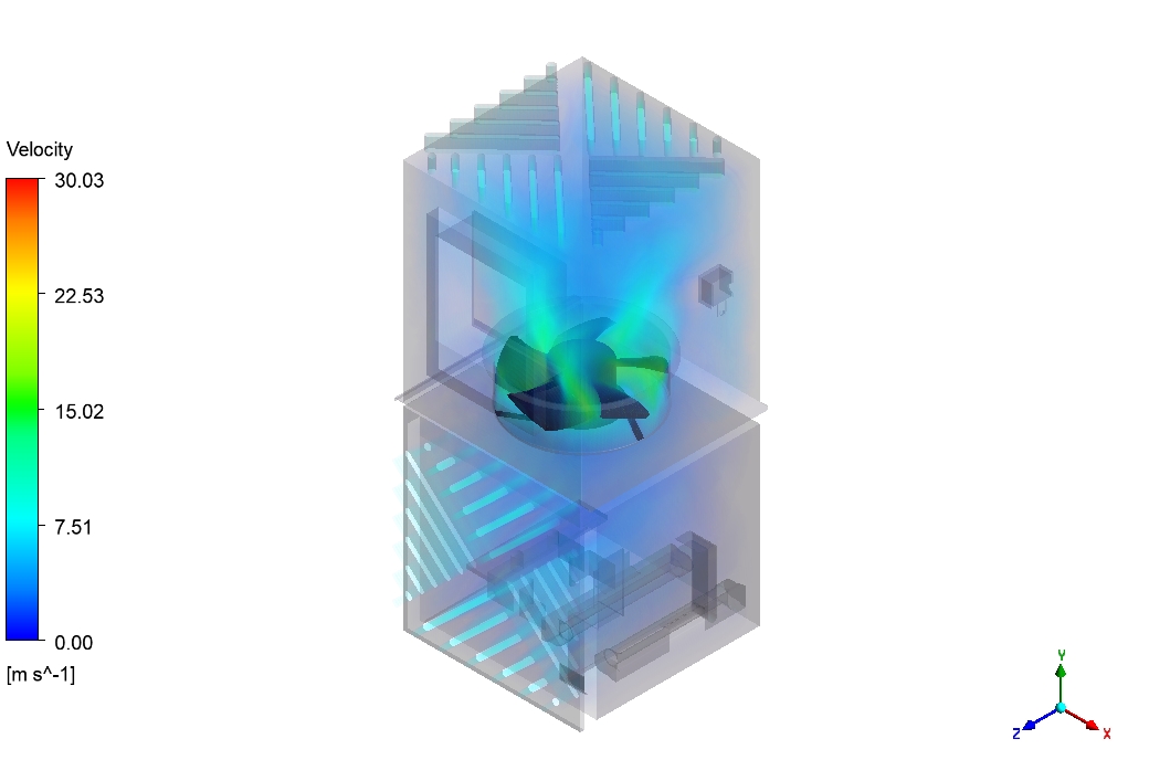
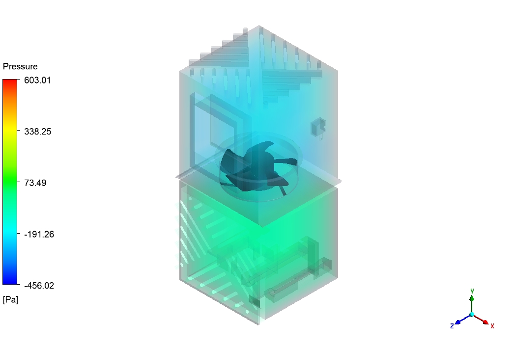
Figure 1: The 3D geometry model used for the Air Purifier Fan Considering Filtration CFD simulation, showing the fan and filter locations.
Simulation Process: Modeling the Fan and Filters in Fluent
To study the Air Purifier Fan Considering Filtration Fluent simulation, we first need a good computer model. We used a 3D model of the purifier, which includes the outer case, the fan, and the filters, as shown in the diagram in Figure 1. In ANSYS Fluent, we must model two very different things. First is the fan, which spins very fast at 3200 rotations per minute (rpm). We model this using a special rotating zone. Second are the filters. The filters are not open space; they are a thick, sponge-like material. To simulate this, we use a Porous Media model. This model tells the computer that these areas will slow the air down and cause a drop in pressure, just like a real filter does. By combining the spinning fan model and the porous filter model, we get a complete and realistic picture of the physics inside the machine.
Post-Processing: How the Fan Fights the Filters to Clean the Air
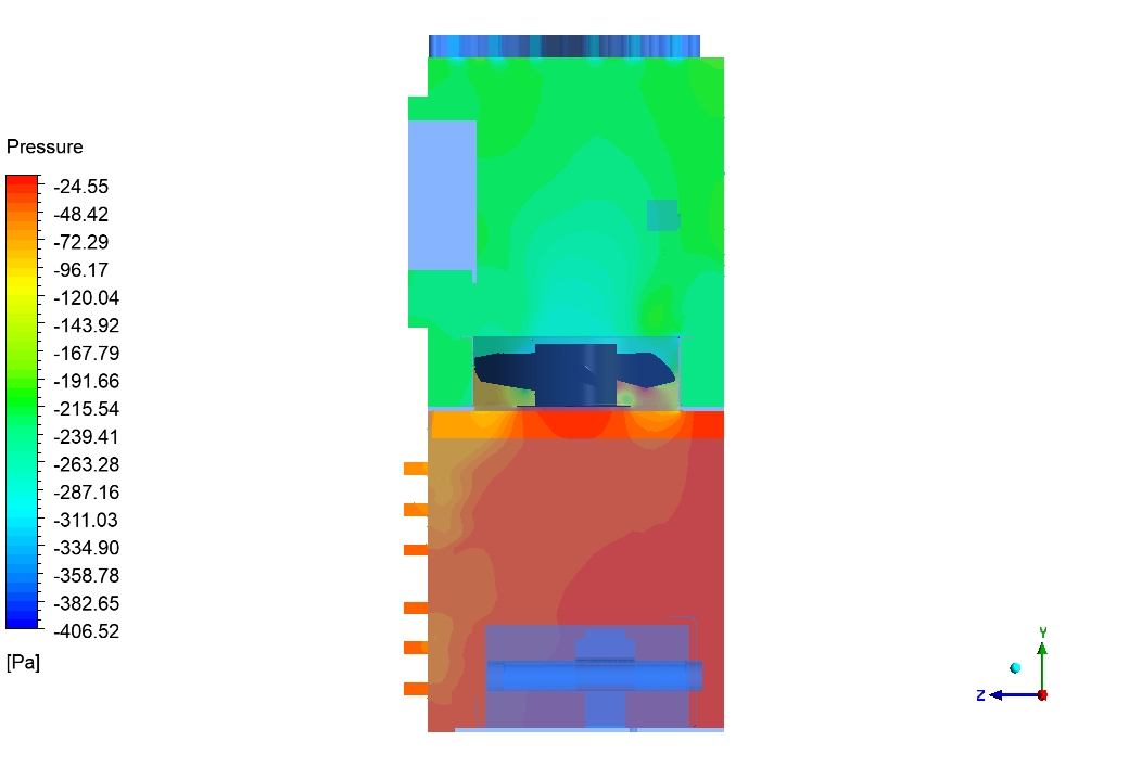
The simulation results tell a clear story of cause and effect, showing the battle between the fan’s power and the filter’s resistance. The main cause of all air movement is the fan. It spins very fast to create a powerful suction. The direct effect is a zone of very low pressure right at the fan’s location. The pressure contour in Figure 3 is the perfect proof. The area around the fan is dark blue, which means the pressure is extremely low (around -400 Pa). This powerful negative pressure is what pulls dirty air into the purifier from the bottom.

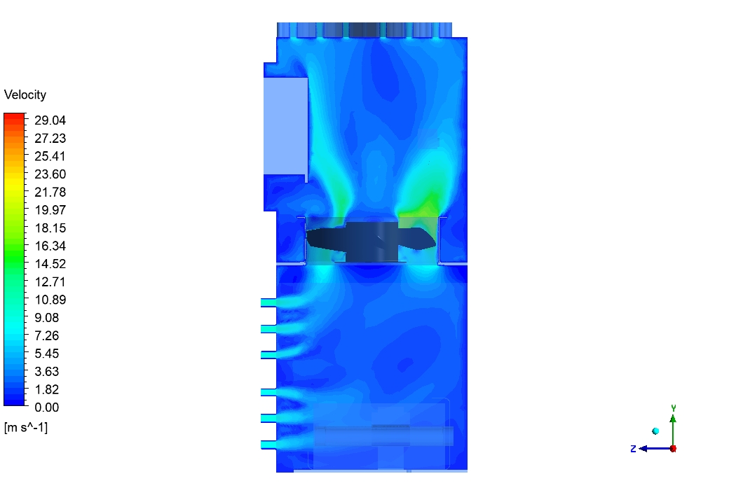
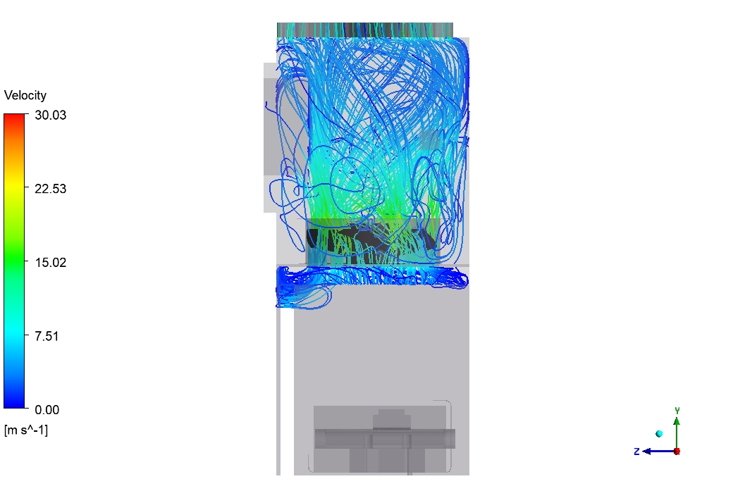
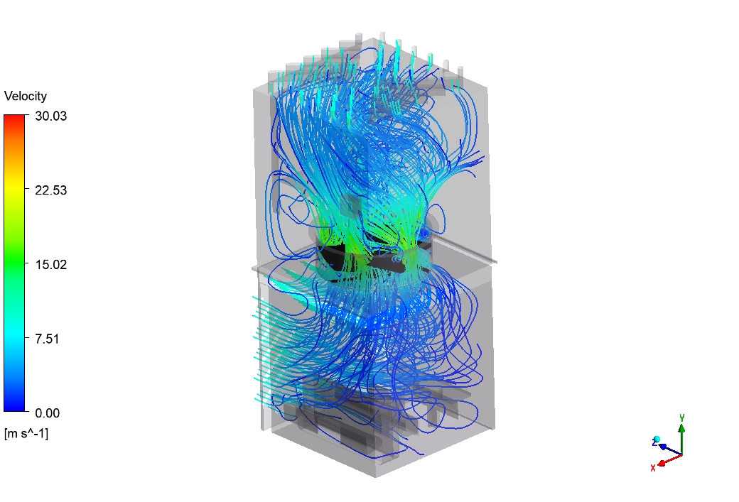
Figure 2: Velocity streamlines from the Air Purifier Fan Fluent analysis, showing air moving fast (green) at the fan and swirling as it passes through the filters.
This suction is the cause of the next action: the air is pulled at high speed toward the fan. The effect is that this fast-moving air then crashes into the filters. The streamlines and velocity contours in Figure 2 show this perfectly. The air moves very fast (green colors, around 15 m/s) right at the fan. But after it goes through the fan and hits the filters, it slows down a lot. It also becomes very swirly and mixed up. This swirling is a good effect, because it helps spread the clean air all around the room when it leaves the top of the purifier. The most important achievement of this Dust Filtration CFD analysis is its ability to precisely measure how hard the fan must work against the filters. The simulation shows that the fan creates a powerful suction (the cause), but this results in a total pressure drop of nearly 400 Pa across the machine (the effect). This huge pressure difference is the price the fan must pay to force air through the dense filters. This number tells engineers exactly how strong the fan needs to be, helping them choose the perfect motor that is both powerful enough to clean the air and quiet enough for a home.
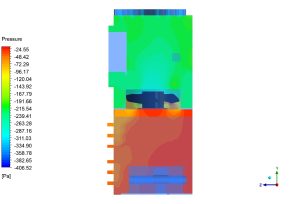
Figure 3: A pressure contour plot from the Filtration Fluent simulation, showing the very low pressure (dark blue) created by the fan’s suction.


Reviews
There are no reviews yet.