


Burning methane (CH4) is a common way to generate energy. When methane mixes with oxygen (O2), it creates Carbon Dioxide (CO2), Water Vapor (H2O), and a lot of heat. This is called an exothermic reaction. In real industrial machines, we rarely use the exact amount of air needed. Instead, we use “excess air” to make sure all the fuel burns completely.
In this Methane Combustion CFD simulation, we model a specific case with 28% excess air. The chemical equation changes because of this extra air. We include Nitrogen (N2) in the reaction because it leads to pollution. The goal of this ANSYS Fluent training is to predict the formation of Nitrogen Oxide (NOx). NOx is a harmful pollutant, and simulating it helps engineers design cleaner burners.
CH4 + 2.56O2 + 9.6256N2 ® CO2 + 2H2O + 0.56O2 + 9.6256N2
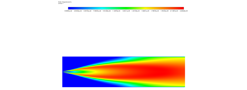
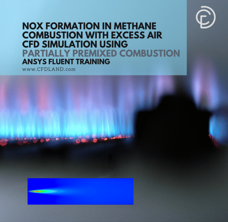
Figure 1: Temperature distribution contour showing high heat release near the burner.
Simulation Process: Modeling Methane Combustion and NOx Formation with Fluent
To start this CFD analysis, we modeled a cylindrical combustor. The geometry is designed for a high-speed jet. Methane is injected into the center and expands without hitting the outer walls too quickly. It mixes with the low-speed air surrounding it. To simulate this accurately, we generated a “structured mesh grid.” This grid covers the whole combustor and consists of exactly 34,100 elements. A structured grid is very important because it helps calculate the flow direction precisely.
For the physics in ANSYS Fluent, we selected the Species Transport model. This model allows the software to track different gases like Methane, Oxygen, and Carbon Dioxide separately. Because the flow is turbulent and reacts chemically, we used the Eddy Dissipation model. This model calculates how the turbulence mixes the fuel and air before they burn. Furthermore, to capture the pollution data, we enabled both Prompt and Thermal NOx formation models. This ensures we see all types of nitrogen oxides created during the heat release.
Post-processing: NOx Formation and Velocity Analysis
In this section, we analyze the results of the Methane Combustion CFD. We look at the connection between heat, speed, and pollution. First, the Temperature Contour (Figure 1) gives us a clear view of the flame. We can see areas of very high temperature located right next to the burner. This indicates the “ignition source” where the reaction starts. As the methane burns, the Mass Fraction of the species changes. At the inlet, the methane concentration is high. However, as it moves downstream, the methane disappears. It is replaced by combustion byproducts like CO2 and H2O. Simultaneously, at these high temperatures, the Nitrogen reacts with Oxygen to form NOx (Nitric Oxide and Nitrogen Dioxide).

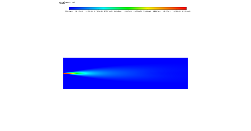
Figure 2 & 3: NOx mass fraction from the NoX Formation CFD analysis, highlighting the regions of high pollutant concentration – Velocity field from the Methane Combustion with excess air CFD simulation, showing the central jet and recirculation zones that influence NOx formation.
Second, we observe a critical link between the Velocity Field and NOx Production. The velocity contour (Figure 3) shows a typical jet pattern. The core of the jet moves very fast, but as it goes further, it slows down. This creates “recirculation zones” on the sides where the air moves slowly and mixes. This flow pattern directly changes the pollution levels. Consequently, the NOx Concentration Contour (Figure 2) shows that the highest pollution is not in the fast jet, but in the “post-flame zone.” This happens because of a concept called “residence time.” In the central jet, the gas moves too fast to react fully with nitrogen. However, in the slow peripheral regions, the hot gas stays for a longer time. This long “residence duration” combined with high temperature creates the perfect condition for Thermal NOx formation via the Zeldovich mechanism. This analysis proves that to reduce pollution, we must control both the temperature and the speed of the gas mixture.


Reviews
There are no reviews yet.