

The Glass Melting Furnace is a fantastic work of industrial engineering. It’s like a crucible where everyday raw materials go through an alchemical change to become the amazing substance glass. In its fiery center, silica sand, soda ash, and limestone are heated to very high temperatures and melt and fuse together into a molten mass that has shaped societies for thousands of years. The furnace is the hidden hero behind many everyday things, from the windows that let light into our homes to the fine china on our tables. It is the basic technology that makes progress possible in many areas, from building and car design to telecommunications and cutting-edge science. As industries change and more specialized glass goods are needed, the furnace stays an important part of the process and is always being improved and rethought to meet the needs of the future. Nevertheless, the key initial step through investigations is CFD modeling. This is our objective in the present study to perform a CFD simulation regarding a valuable reference paper “Numerical simulation and experimental analysis of an industrial glass melting furnace [1]”. It is worth saying that our model geometry is designed based on a real industrial apparatus.
- Reference [1]: Abbassi, A., and Kh Khoshmanesh. “Numerical simulation and experimental analysis of an industrial glass melting furnace.” Applied Thermal Engineering5-6 (2008): 450-459.
Figure 1: Glass Melting Furnace CFD Simulation, ANSYS Fluent Training
Simulation Process
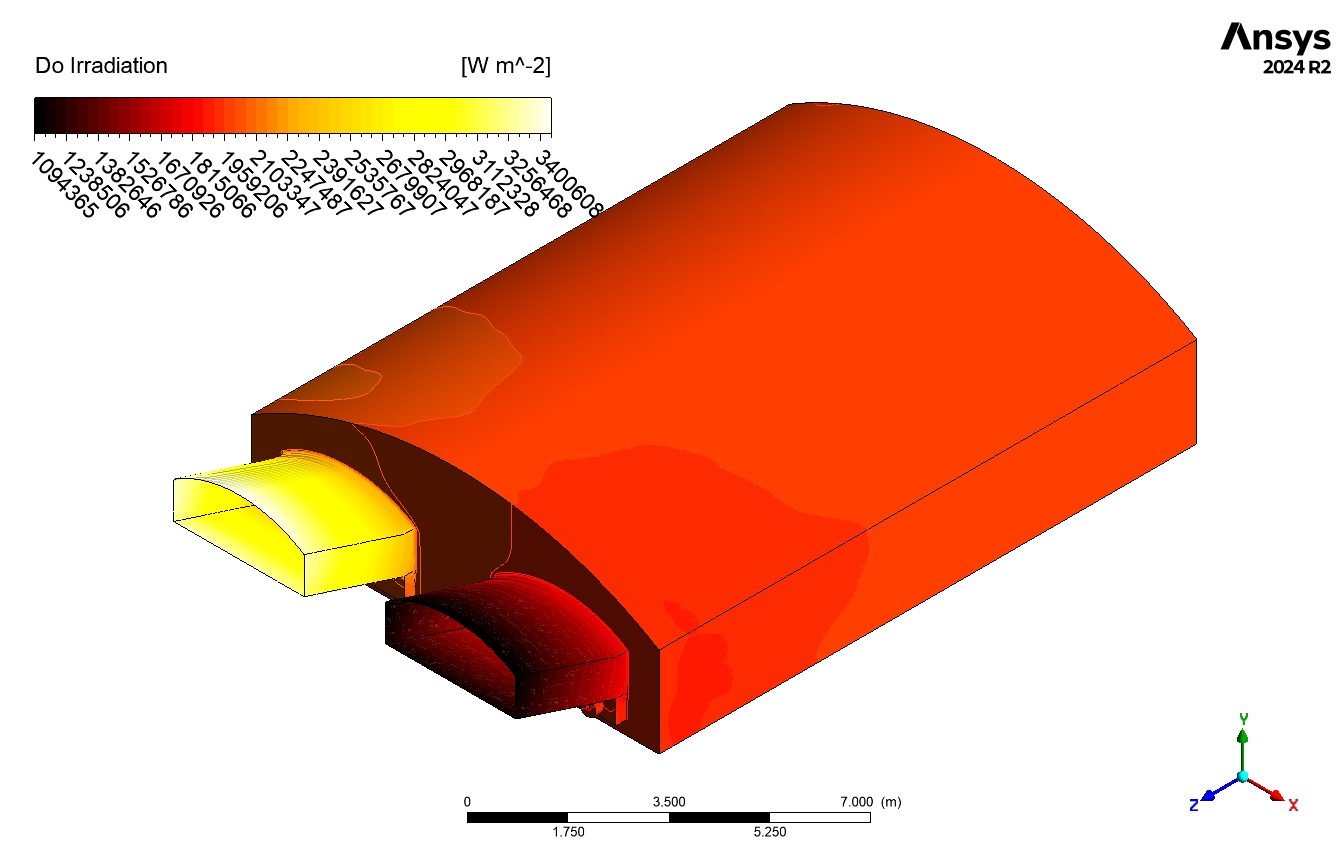
As already discussed, the geometry model designed based on a real industrial model. It then meticulously meshed in ANSYS Meshing to provide a fine structured grid, resulting in 2541440 hexagonal cells, as depicted below. It is necessary to follow the reference model. Thus, Species transport model, following Volumetric reactions are set. Plus, the discrete ordinates (DO) radiation model was used to simulate the exchange of radiation between hot gases, because it`s not negligible in regions near the furnace. The reaction takes place regarding the following reaction equation:
CH4 + O2 ==> Co + H2O
Note that, there are plenty of effective thermophysical properties and models that has to be determined carefully.
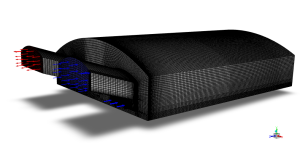
Figure 2: Structured grid over Glass Melting Furnace CFD Simulation
Post-processing
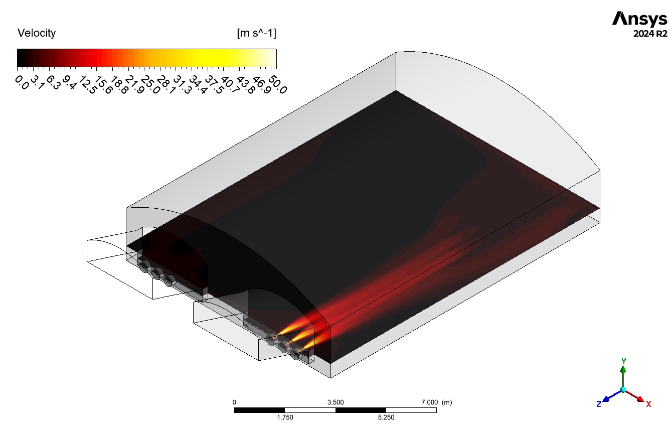
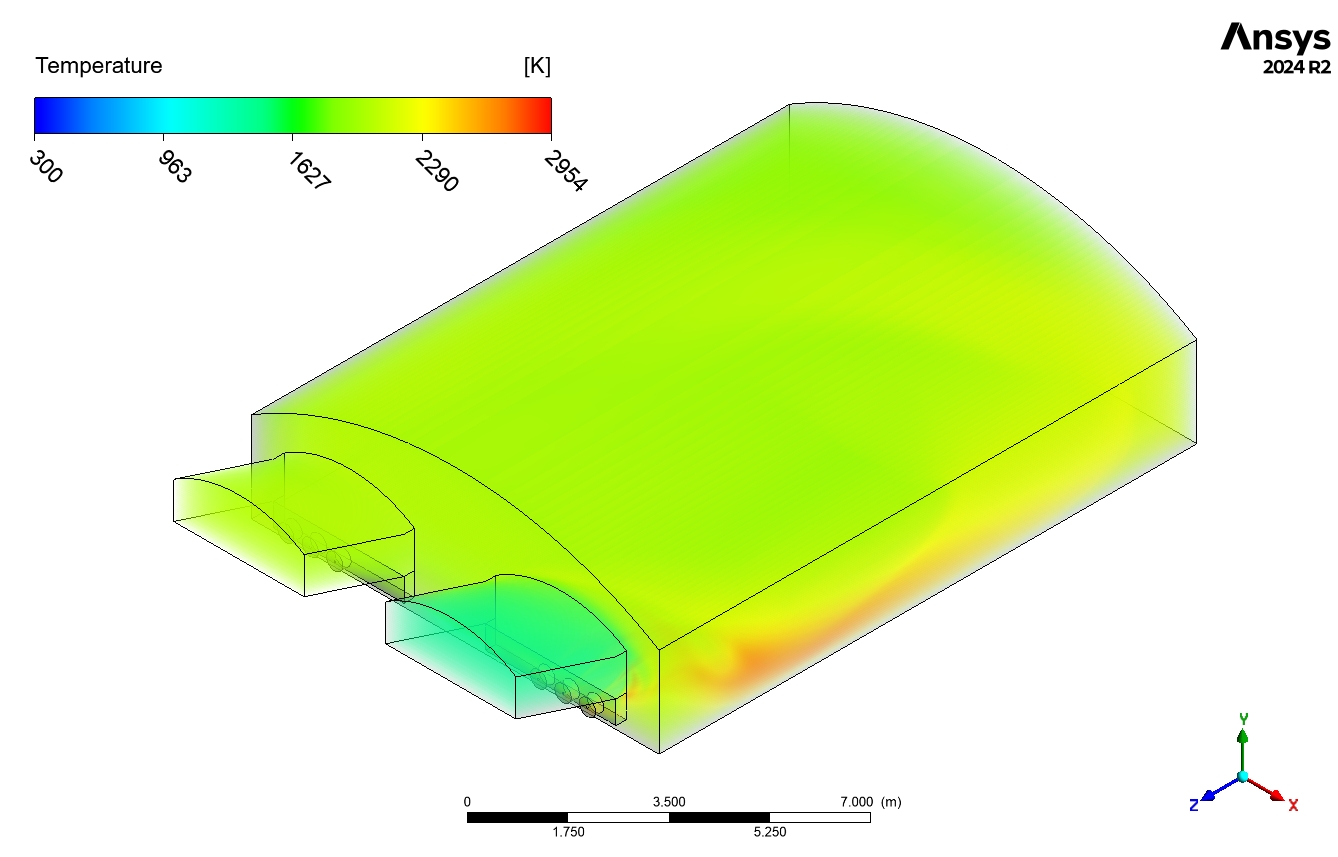
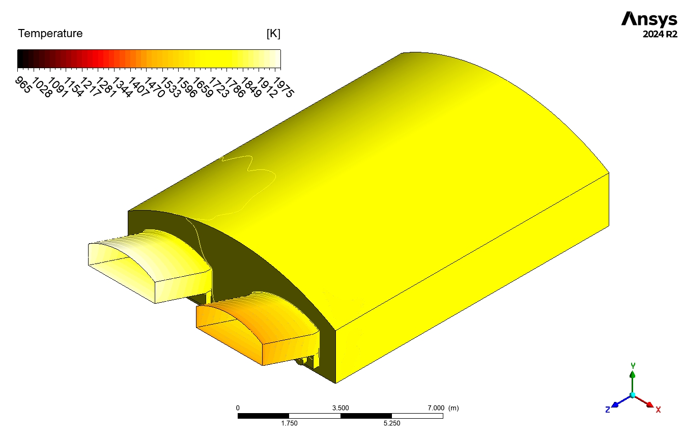
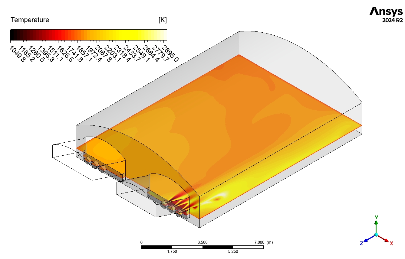
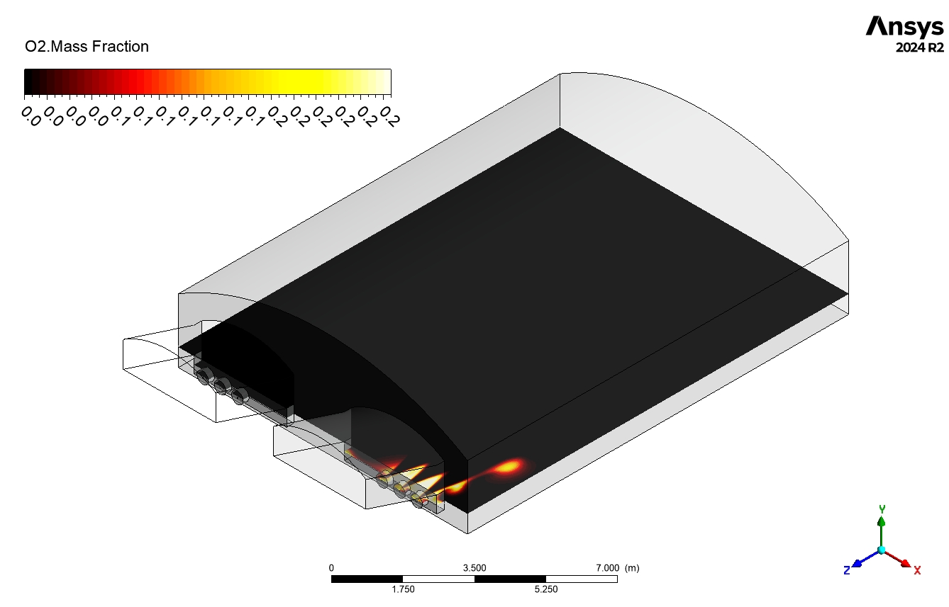
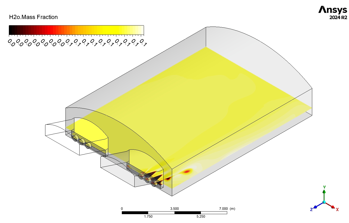
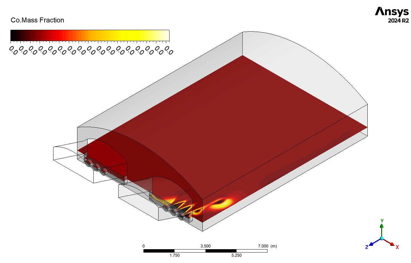
The simulation results show a peak temperature of 2016.74K close to the furnace exit, which means the temperature is high enough for glass to melt. The velocity curve (Fig. 3) shows the flow pattern inside the furnace. Faster speeds are seen near the intakes, while a more complicated, recirculating flow forms in the main chamber. This recirculation is very important for efficiently moving heat and making sure that temperatures are spread out evenly, which helps keep the quality of the glass steady. The CH4 mass fraction contour (Fig 4) shows how methane, the main fuel component, is spread out, with higher amounts near the inlets where it is injected. As you move toward the outlet, the declining concentration of CH4 shows that the combustion is going well. The CO mass fraction contour backs this up; it shows that there is more CO near the burners, which means that there is ongoing combustion there. The fact that the CO levels are going down further into the furnace suggests that the fuel has been completely burned and is being mixed well.

Figure 3: Velocity in glass melting furnace tank CFD Simulation
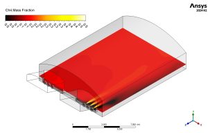
Figure 4: CH4 mass fraction contour in glass melting furnace tank
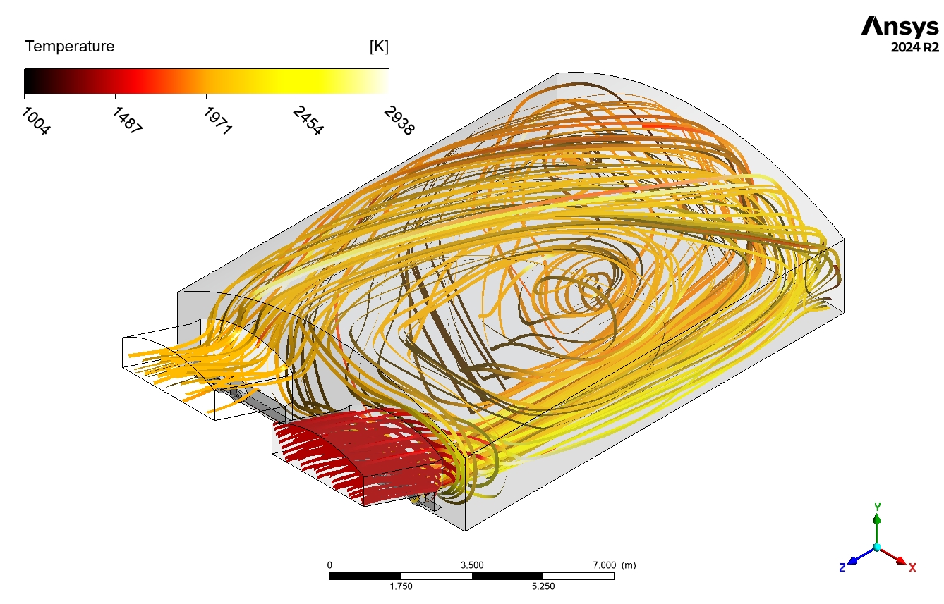
The temperature contour (Fig. 5), which shows the heat produced by combustion, backs this up even more. The temperatures are highest near the combustion zones and gradually drop as you move away from the exit. The streamline outline shows the path of the gases, showing the areas where they flow over and over again and how the flow behaves overall. The way the velocity, temperature, CH4, and CO concentrations interact shows how well the combustion process and heat movement work inside the furnace. It is possible to see recirculation zones in the velocity and streamline outlines. These help mix the reactants well and heat the glass melt evenly. The fact that CO levels rose near the burners and then fell again shows that the fuel was completely burned and mixed well, which helps heat transfer and production work at their best.


Reviews
There are no reviews yet.