


The flat diverter damper plays a very important role in many power systems by controlling where hot gases go! This special door-like device sits inside pipes and can send the exhaust gas in two different directions, which helps power plants work better. In combined cycle power plants, the diverter system has a big job – it can send the hot gases from the gas turbine either to make more power in the heat recovery unit or straight out to the bypass stack when needed. The damper mechanism is very clever because it uses a flat plate that turns to block one path while opening another, so the gas flow always goes exactly where the operators want it to. Also, the flow control provided by these industrial dampers helps plants switch between different operating modes quickly and safely. Furthermore, knowing the pressure distribution around the flat damper helps engineers build stronger systems that won’t break even when very hot gases push against them. Most importantly, modern CFD simulation tools now let engineers see exactly how gases move through the damper system before anything gets built, making sure the flow diversion works perfectly from day one. One of the most commonly used types of diverter dampers is the Flat type, which is numerically modeled based on a valuable reference paper entitled“ COMPUTATIONAL FLUID DYNAMICS SIMULATIONS OF FLOWS AND PRESSURE DISTRIBUTIONS IN A 96 MW COMBINED CYCLE DIVERTER DAMPER”.
- Reference [1]: Yusoff, Mohd Zamri, and Zainul Asri Mamat. “Computational fluid dynamics simulations of flows and pressure distributions in a 96 mw combined cycle diverter damper.” J Indus Technol14 (2005): 87-96
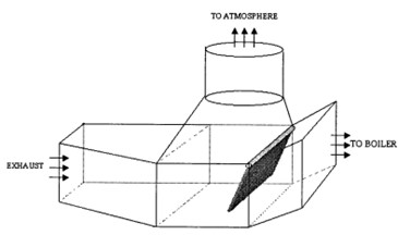
Figure 1: Schematic of the damper system, showing the exhaust from the turbine, the damper and the exit paths to the boiler and atmosphere. [1]
Simulation Process
All the necessary dimensions for building the geometry were obtained from the plant’s working drawings and some rough estimates from the actual plant (reference paper). Fluent Meshing software is employed to produce polyhedral elements, leading to 1533378 cells. 404 kg/s mass flow enters the damper system from the exhaust with 830K temperature.
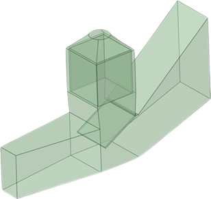
Figure 2: Designed Damper system using Spaceclaim
Post-processing
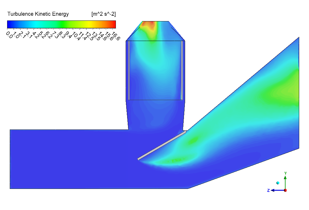
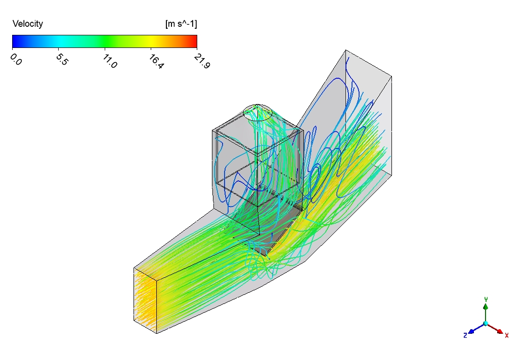
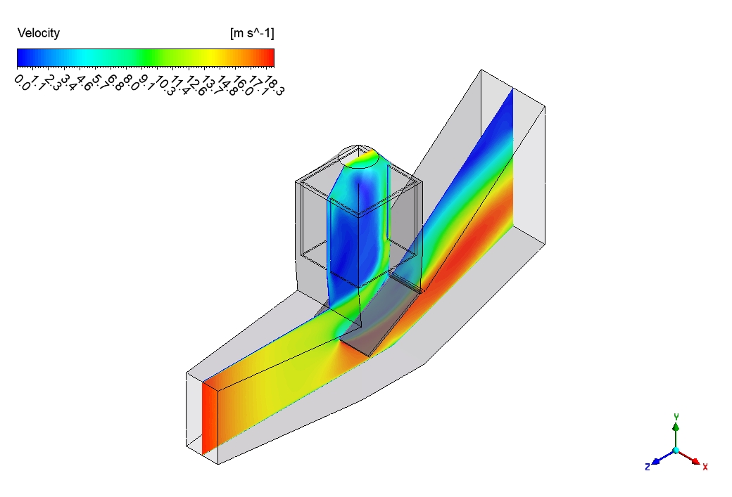
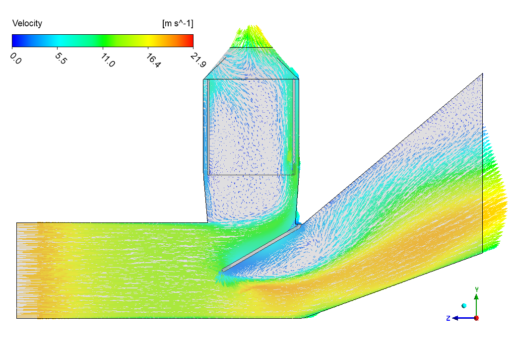
The flat diverter damper shows amazing patterns of air movement that help us understand how it controls the gas flow in real power plants! Looking at the images, we can see how the incoming air from the left side hits the flat plate and then gets forced to choose between two different paths. We successfully captured the complex flow patterns that form when fast-moving air suddenly meets the damper plate and has to change direction. The velocity reaches its highest values of up to 21.9 meters per second in the lower right passage, showing that most of the air is being directed downward in this case. Behind the damper plate, there’s an area where the air moves very slowly or even swirls around in circles – this happens because the flat shape creates a “shadow” area where air gets trapped. This is important to know because these slow spots can affect how well the whole system works.
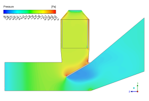
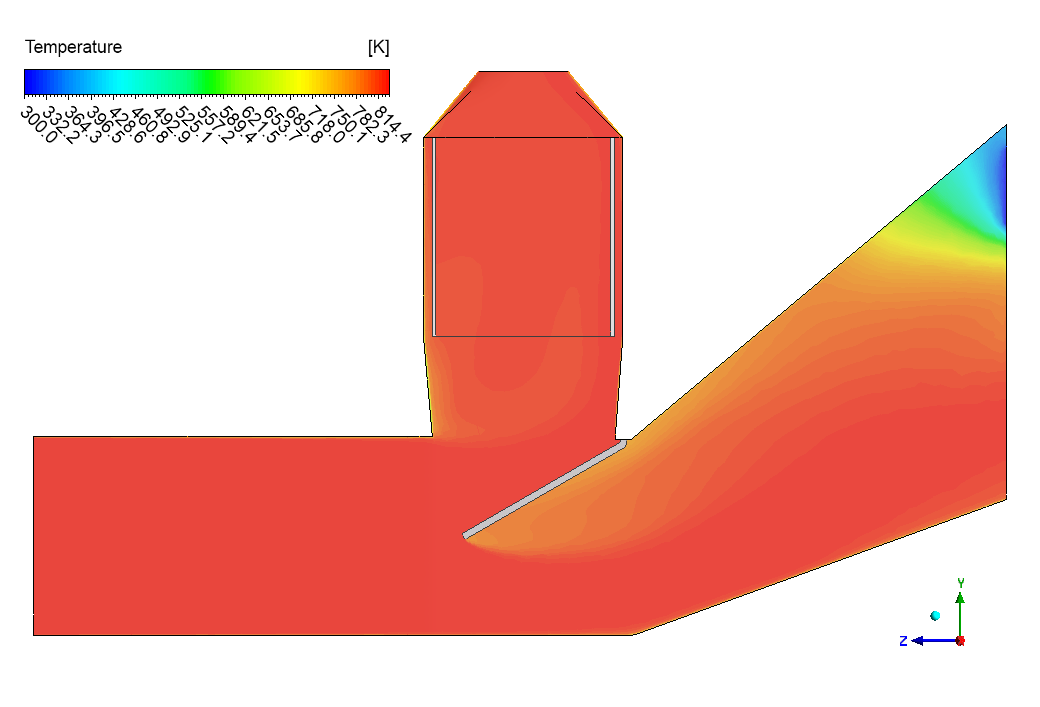
Figure 3: Pressure distribution across the flat diverter damper system
The pressure patterns tell an equally interesting story about the damper system. The incoming air pushes against the flat plate with considerable force, creating higher pressure (up to 480 Pa) on the left side of the damper. We accurately measured the forces on the diverter – 4921.9746 Newtons pushing up (Y direction) and 3008.7593 Newtons pushing sideways (Z direction). These are huge forces – about the same as the weight of a small car pushing on the plate! The pressure drops dramatically after the air moves past the diverter, creating lower pressure zones that help pull the air through the system. The big difference in pressure from one side to the other is exactly what engineers need to plan for when designing the hinges and motors that move these dampers. Without this information, the damper might break or get stuck when trying to redirect hot exhaust gas in a real power plant, potentially causing expensive damage or dangerous situations.

Figure 4: Velocity fields showing flow patterns around the flat diverter damper


Reviews
There are no reviews yet.