


Natural draft cooling towers (NDCTs) represent critical infrastructure in power generation facilities, utilizing buoyancy-driven airflow to dissipate waste heat without mechanical assistance. This simulation investigates the complex phenomenon of flue gas injection into NDCTs, a practice that allows power plants to utilize existing cooling tower structures as emission stacks while potentially reducing visible plume formation. The analysis examines the thermal-flow characteristics and pollutant dispersion patterns created when hot flue gases containing various contaminants interact with the cooling tower’s natural draft. Understanding this interaction is essential for predicting both the cooling efficiency impact and environmental consequences of combined cooling and emission systems. Based on the reference papers, our simulation employs advanced computational models to capture the buoyancy effects, thermal stratification, crosswind influences, and emission characteristics that determine the overall performance of these hybrid systems.
- Reference [1]: Yang, Guangjun, et al. “CFD simulation of pollutant emission in a natural draft dry cooling tower with flue gas injection: Comparison between LES and RANS.” Energies19 (2019): 3630.
- Reference [2]: Klimanek, Adam, Michał Cedzich, and Ryszard Białecki. “3D CFD modeling of natural draft wet-cooling tower with flue gas injection.” Applied Thermal Engineering91 (2015): 824-833.
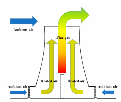
Figure 1: schematic diagram of flue gas emission in natural draft dry cooling tower (NDDCT) with flue gas injection
Simulation Process
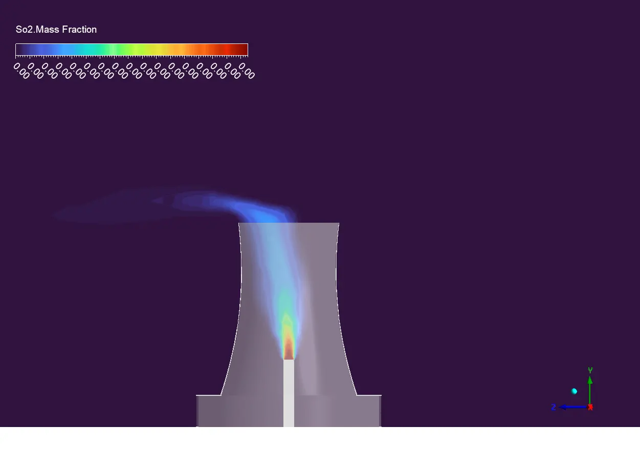
The computational domain represents a natural draft cooling tower with surrounding atmospheric region, created using ANSYS SpaceClaim. The 3D cooling tower geometry includes the distinctive hyperbolic shell structure, heat exchanger region, and flue gas injection ports positioned according to the reference paper specifications. Meshing is performed in ANSYS Meshing with a hybrid approach. A custom User Defined Function (UDF) is implemented to define the atmospheric boundary layer profile at the domain inlet, accurately representing the logarithmic wind velocity variation with height according to standard atmospheric conditions. The species transport model is activated to track multiple gas components including CO2 and SO2 from the flue gas injection, allowing for detailed pollution dispersion analysis.
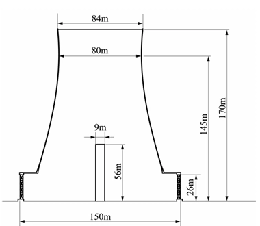
Figure 2: Main dimensions of NDDCT with flue gas injection
Post-processing
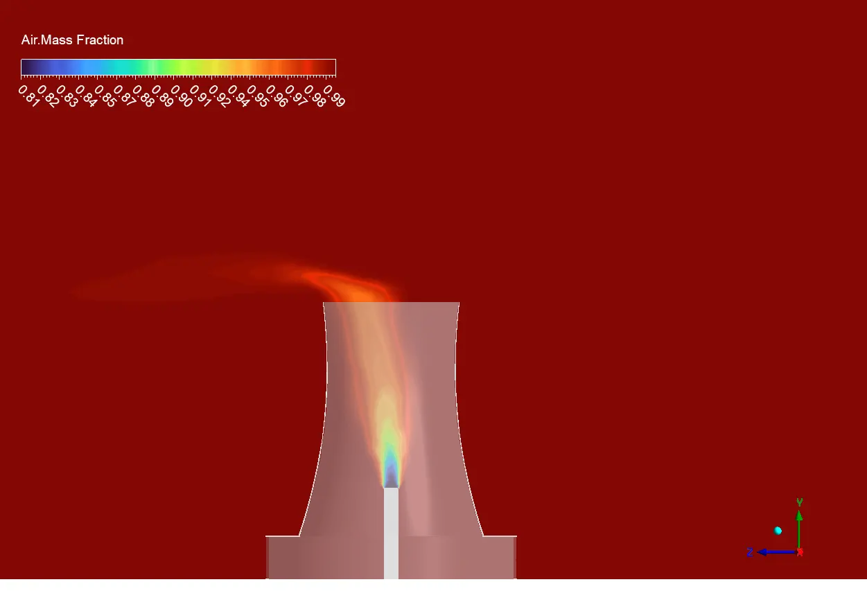
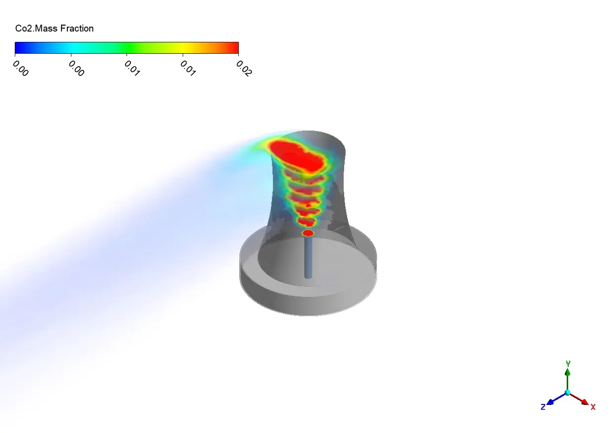
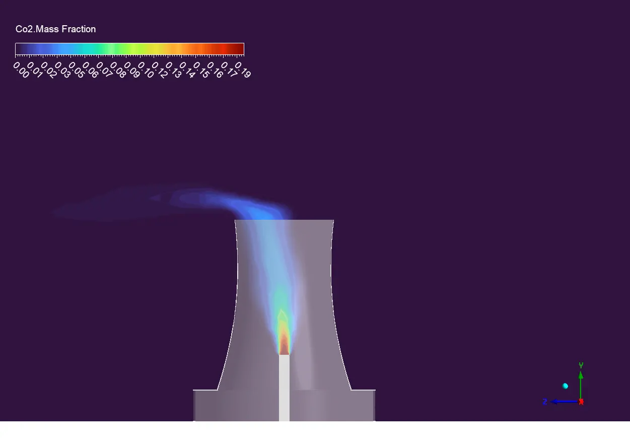
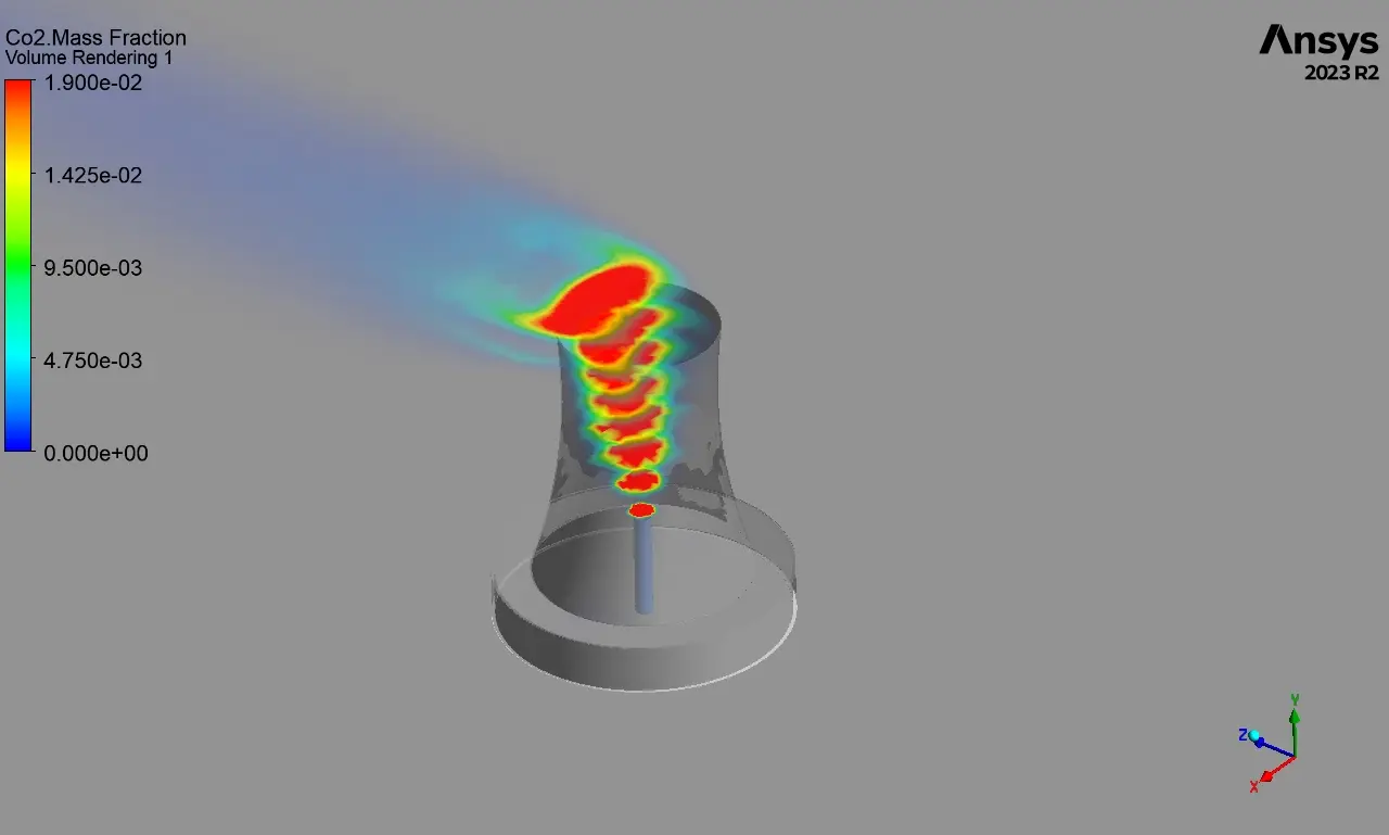
The temperature contours show the unique thermal structure inside and above the cooling tower. At the point where the flue gas is injected, temperatures hit their highest point of about 503K. It is easy to see how natural draft works because the difference in temperatures causes hot gases to rise through the tower’s parabolic structure. At the tower exit, temperatures are still high (380–420K), which makes a noticeable thermal plume that spreads out horizontally because of the crosswind. This horizontal deflection is very important for figuring out the downwind effect zone for thermal pollution reasons. The spread of the CO₂ mass fraction matches the thermal behavior. Concentrations peak at about 0.19 near the injection point and gradually drop to 0.10-0.12 at the tower exit. The species transport simulation correctly shows the concentration gradient as CO₂ rises into the air. The plume pattern shows that it spreads more in the crosswind direction while keeping the core concentration stable for long distances downwind.

Figure 3: Co2 dispersion in cooling tower
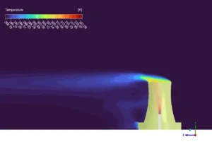
Figure 4: Temperature field around the cooling tower
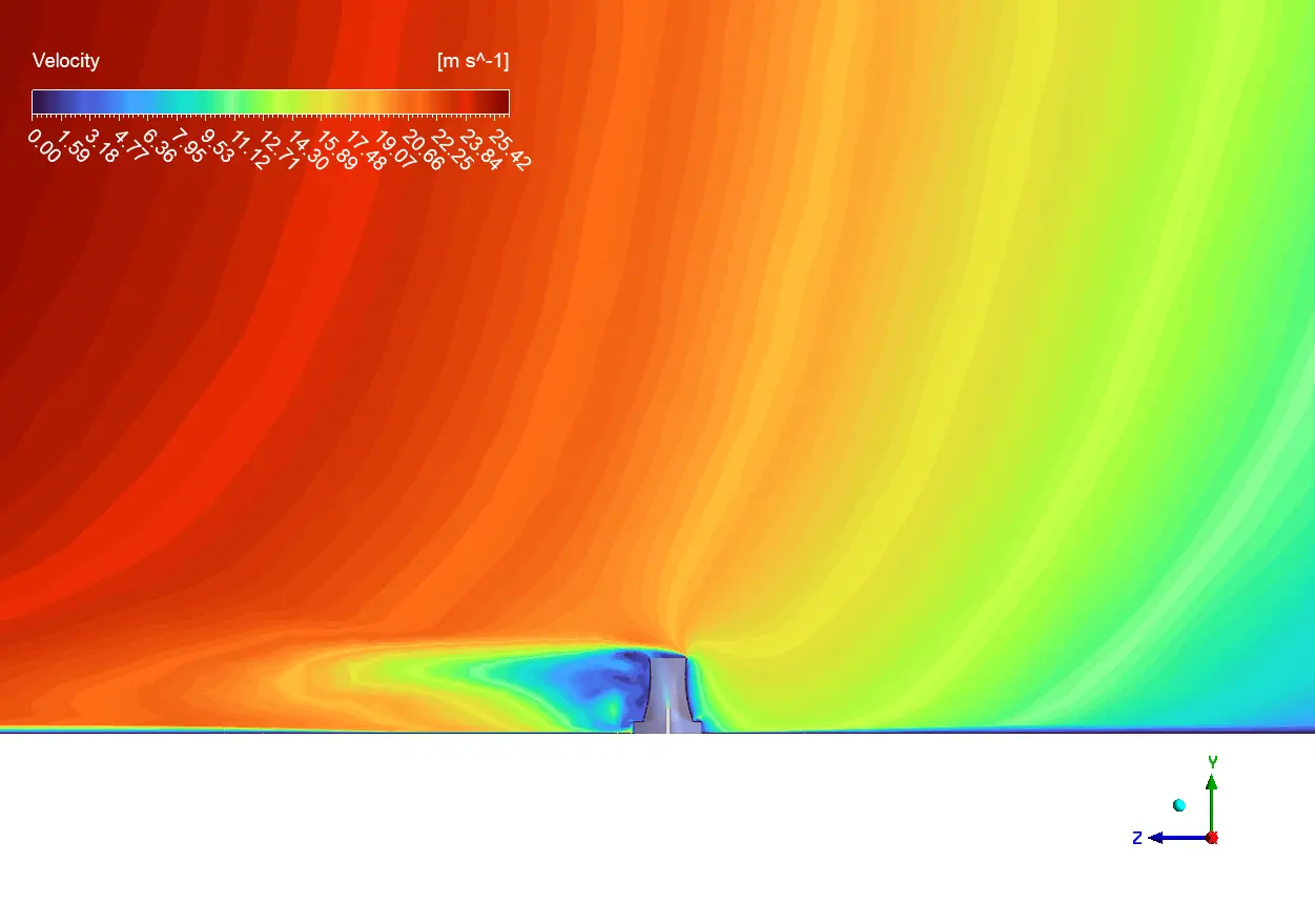
The image of the velocity field shows how the buoyancy-driven upward flow inside the tower interacts with the wind field outside, which gives us important information about how the flow works. Low speeds (2–5 m/s) near the base of the tower allow the injected flue gases to mix properly. As you move toward the exit of the tower, the flow speeds up to 10-15 m/s due to the chimney effect and the tower’s shrinking shape. When crosswinds hit the tower structure, they create unique flow patterns. These include speeding up around the tower’s edge (up to 20–25 m/s) and creating recirculation zones in the downwind wake region. These results show that the idea of a combined cooling tower and flue gas discharge effectively spreads pollutants at higher elevations compared to traditional stacks. However, it is still important to pay close attention to the weather in the area to keep ground-level pollutant concentrations as low as possible.


Reviews
There are no reviews yet.