


Heat-recirculating combustors are a new type of combustion technology that strategically recovers thermal energy from combustion products and sends it to heat up arriving reactants. This makes the combustion process more stable and efficient overall. Based on the breakthrough work of Weinberg and his colleagues, these systems use the enthalpy of combustion products to raise the temperature of new fuel-air mixtures. This lets combustion happen in conditions that would normally be too dry to be volatile. Our study uses a multi-injector setup in this heat-recirculation framework, building on the theoretical and experimental grounds set by Ju and Xu (2005) in their reference paper “Theoretical and Experimental Studies on Mesoscale Flame Propagation and Extinction.” This arrangement sets up recirculation zones that are placed in a way that not only improves the mixing of fuel and air, but also makes it easier for the important heat transfer processes that make these systems work. The use of multiple injectors in a heat-recirculating design shows promise for uses that need small combustion systems that are highly efficient and produce few emissions, especially in power generation and transportation systems that are used on a small scale.
- Reference [1]: Ju, Yiguang, and Bo Xu. “Theoretical and experimental studies on mesoscale flame propagation and extinction.” Proceedings of the Combustion Institute2 (2005): 2445-2453.
Figure 1: Configuration of heat-recirculating combustor with multiple injectors [1]
Simulation process
To start the CFD simulation, a detailed geometric model of the heat-recirculating combustor with multiple injectors was made. This model was then meshed using ANSYS Meshing to make a high-fidelity computational region with 7,765,591 cells for accurate flow resolution. We used the Species Transport Module in ANSYS Fluent to model the volumetric reactions between butane and oxygen in the combustion box so that we could understand how the combustion worked.
C₄H₁₀ + O₂ → CO₂ + H₂O
Since reactive flow simulations of this level of complexity have a high chance of numerical divergence, we used a pseudo-transient method and carefully managed the Courant number to make sure the solution was stable while still being physically accurate. The Eddy Dissipation describe was used to describe the interactions between turbulence and chemistry. This model correctly shows how turbulent mixing affects reaction rates in this situation. One thing that made our simulation stand out was that it included aluminum fins inside the combustion chamber.
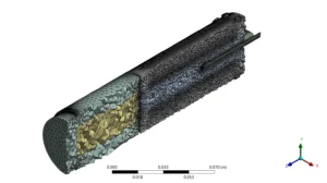
Figure 2: Grid over Heat-recirculating Combustor with Multiple Injectors
Post-processing
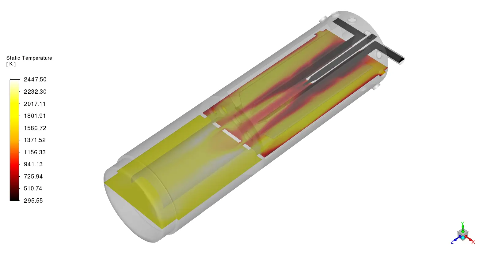
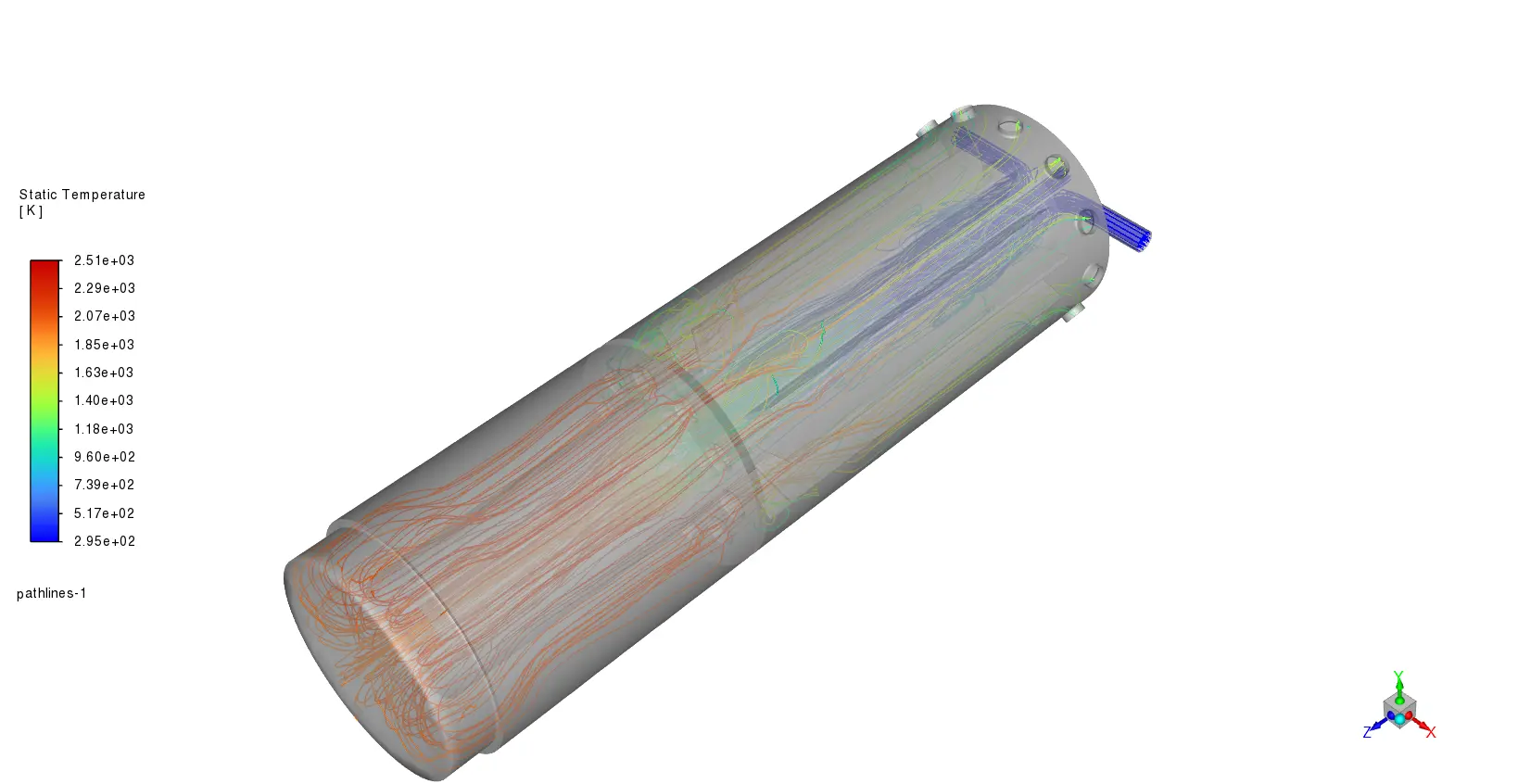
The CFD modeling results show that the heat-recirculating combustor has complex flow dynamics that have a big effect on its thermal performance. The temperature curves show a clear thermal gradient starting from the multiple injection points, with temperatures ranging from 300K at the inlet to peak temperatures of over 2100K in the primary reaction zones. This is because the aluminum fins effectively transfer heat from areas with high temperatures back to the incoming reactant mixture. Visualization of velocity vectors shows that clear recirculation zones form downstream of each injector, with main recirculation speeds of around 15 to 20 m/s. These zones create important flow patterns that increase residence time and encourage full combustion. The opposing vortex pairs formed between neighboring injectors create shear layers that make turbulent mixing stronger. This is shown by the fact that turbulent kinetic energy values (0.5–0.8 m³/s²) are higher in these areas. The fact that the temperature increase in the pre-reaction zone was about 400K higher than in traditional designs that don’t use heat circulation is important for engineers because it proves that the heat-recirculation idea works. The aluminum fins have a maximum surface temperature of about 1800K and improve the effective heat transfer surface area by 22%. This proves that they play a part in improving thermal efficiency.

Figure 3: Temperature field inside Heat-recirculating Combustor with Multiple Injectors
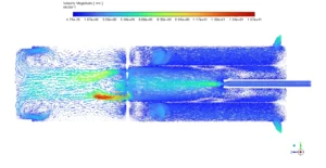
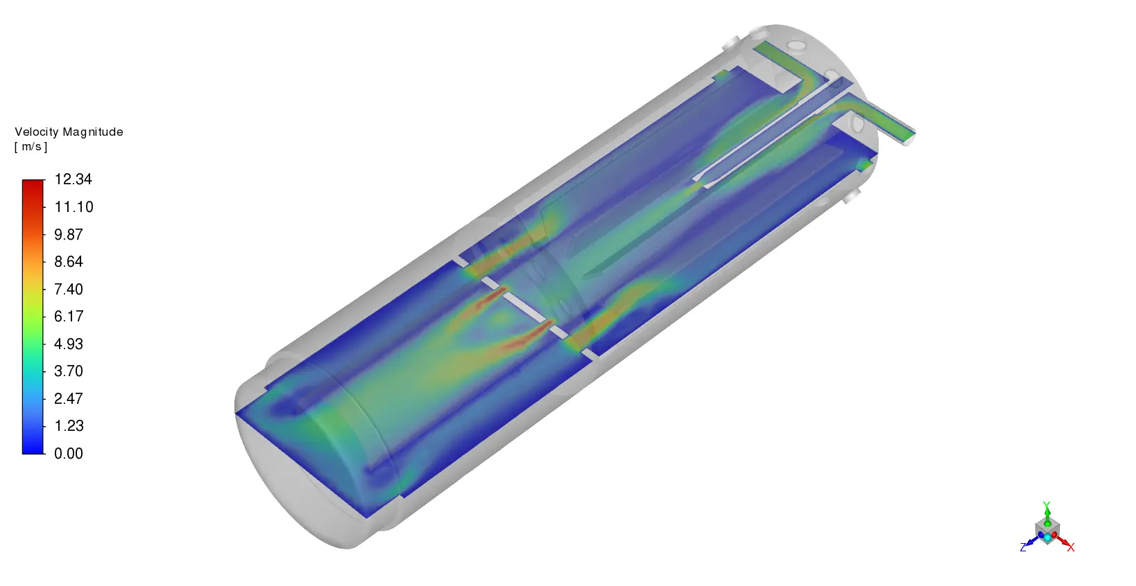
Figure 4: Circulation pattern inside Heat-recirculating Combustor with Multiple Injectors
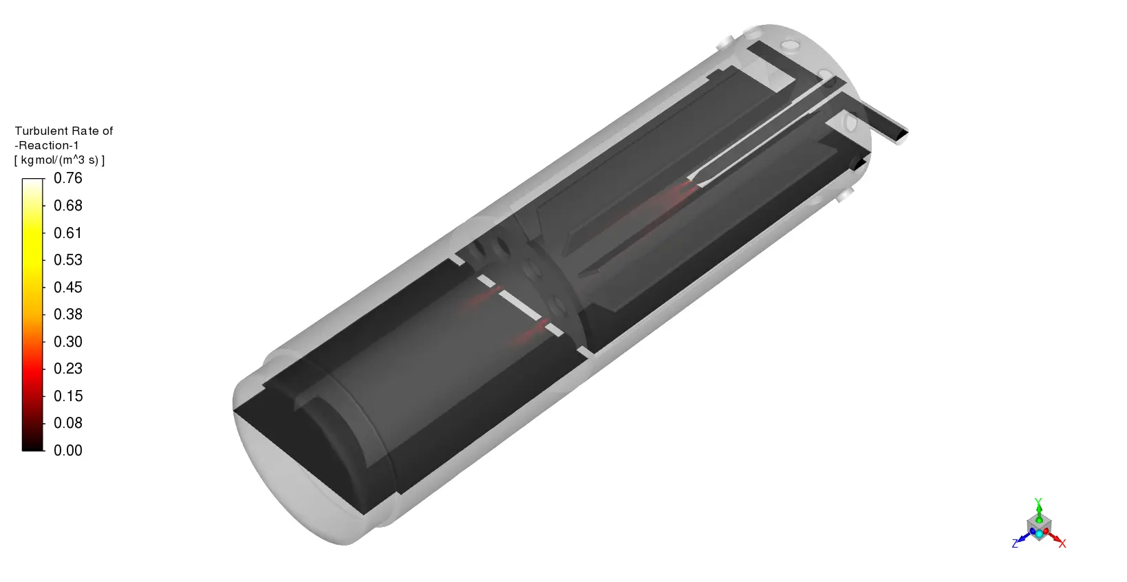
The profiles of species concentrations show that combustion is very efficient throughout the chamber, with conversion rates of C₄H₁₀ reaching 98% downstream of the main reaction zones. The multiple injectors set up makes a spread-out response profile that stops hot spots from forming. The highest temperature differences stay below 300K/mm, which lowers the thermal stresses on the chamber walls. The concentration curves for CO₂ and H₂O show that formation progresses along the length of the chamber, reaching peak mass fractions of 0.15 and 0.12, respectively, which is in line with what theoretical stoichiometry says should happen. The eddy dissipation model correctly predicted how turbulence and chemistry interact. This is shown by the reaction rate curves, which show that combustion is stronger in areas with a lot of turbulent kinetic energy. A study of pressure drop shows that the combustor has a mild total pressure loss of 3.5%, which is fine considering the better thermal performance. Placing aluminum fins in the right places makes thermal bridges between the hot byproducts of combustion and the new reactants coming in. The heat flux readings at the fin surfaces are about 120 to 150 kW/m². This setup successfully expands the combustor’s working range to include fuel-air mixtures that are below normal flammability limits.


Reviews
There are no reviews yet.