


Hydrogen is one of the most important clean energy sources for the future. To produce hydrogen, industries use a process called Steam Methane Reforming (SMR). This process happens inside giant machines called Side-Fired SMR Furnaces. Inside these furnaces, high heat and a special catalyst turn natural gas (methane) and steam into hydrogen and carbon monoxide. These furnaces are essential for oil refining, chemical plants, and power generation. However, designing them is difficult because the temperatures are extreme. Engineers cannot easily look inside to see if the design is working. Therefore, we use a Side-Fired SMR Furnace CFD Simulation to visualize the process.
In this tutorial, we use ANSYS Fluent to create a 3D simulation of the furnace. We base our investigation on a valid scientific paper titled “Optimal Tube Bundle Arrangements in Side-Fired Methane Steam Reforming Furnaces” by Engel et al. This ensures our simulation uses realistic data. The goal is to perform a complete thermal and hydrodynamic analysis. We want to understand how the hot gases move (hydrodynamics) and how the heat travels to the tubes (thermal analysis). This helps us design furnaces that produce more hydrogen for less money. For more examples of combustion and reacting flows, please explore our Combustion CFD tutorials.
- Reference [1]: Engel, Sebastian, et al. “Optimal tube bundle arrangements in side-fired methane steam reforming furnaces.” Frontiers in Energy Research8 (2020): 583346.
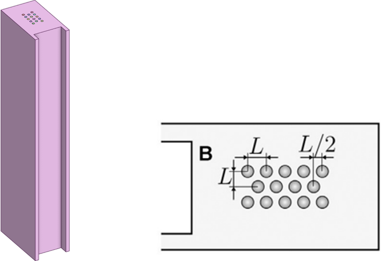
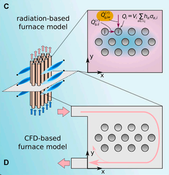
Figure 1- Sketch of a radiation-based and CFD-based furnace model extracted from the paper mentioned in reference [1].
Simulation Process: Mesh and Physics Setup for SMR Analysis
For this SMR Furnace CFD Simulation, we started by building the geometry in ANSYS Design Modeler. The design features a specific array of tubes located in the center of the furnace, based on “Design B” from our reference paper. We then moved to ICEM software to generate the mesh. We did not use the standard mesher because we needed a high-quality structured grid. We generated a very dense mesh with 4,012,428 elements. A mesh of this size is essential. In thermal simulations involving radiation, a coarse mesh can lead to incorrect temperature results.
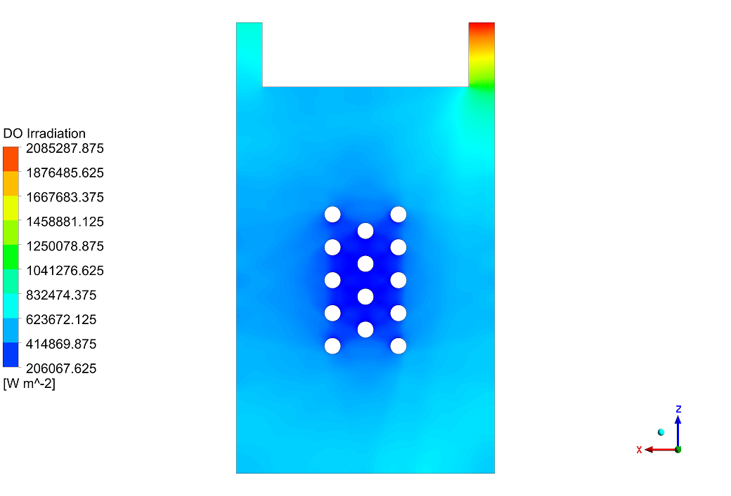
The most critical part of this tutorial is the physics setup in ANSYS Fluent. Because the temperature is very high, radiation is the main way heat moves. Therefore, we activated the Discrete Ordinates (DO) Radiation Model. This model is precise enough to calculate how heat rays travel through the gas. We also enabled the Species Transport Model. This allows us to simulate the mixture of different gases. We defined a mixture consisting of Water Vapor (H2O), Oxygen (O2), Carbon Dioxide (CO2), and Nitrogen (N2). Finally, we set the absorption coefficients of these gases to change with temperature, and defined the furnace walls as “adiabatic,” meaning no heat can escape to the outside world.
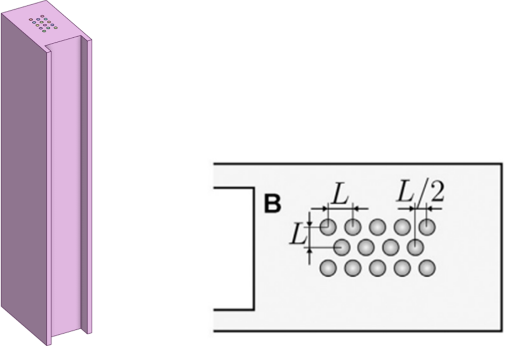
Figure 2- The 3D geometry of the furnace created in Design Modeler, showing the complex tube bundle arrangement in the center.
Post-processing: Hydrodynamic and Thermal Analysis of the Reformer
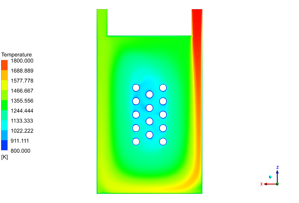
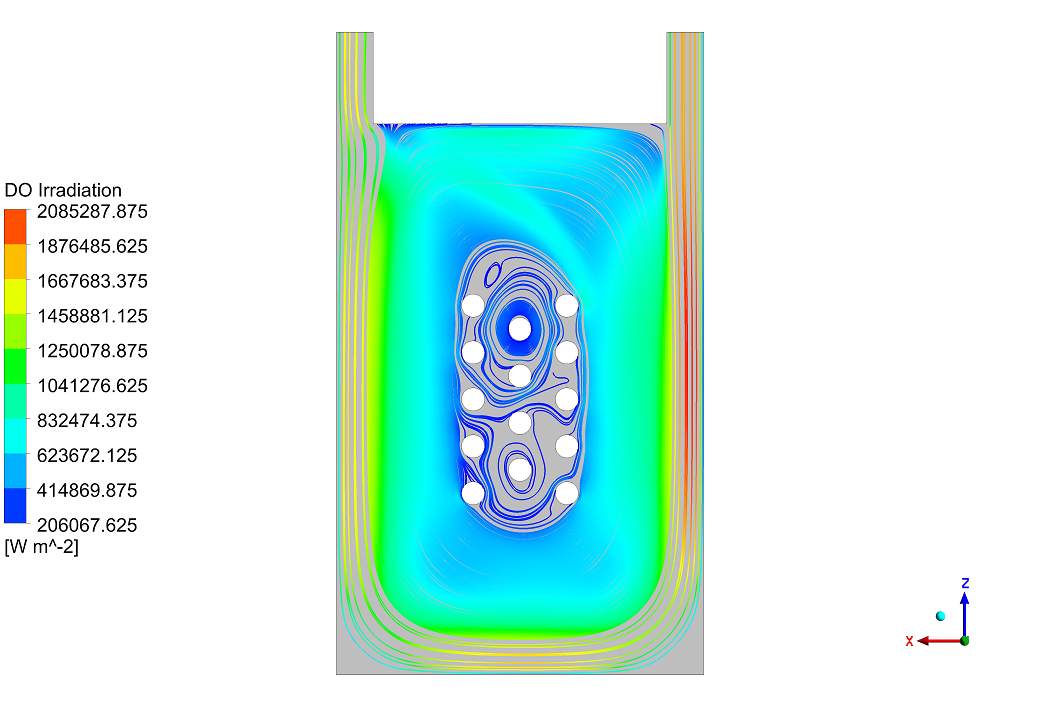
The results of the SMR Furnace CFD Simulation reveal important details about how the gas moves and heats the tubes. By looking at the velocity distribution in Figure 3, we can see a wide range of speeds. The gas enters the furnace very fast, reaching a maximum velocity of 17.5 m/s at the flue gas inlet. However, as the gas moves deep into the tube bundle, it slows down significantly. In the narrow spaces between the tubes, the velocity drops to almost 0 m/s, creating stagnation points. This flow pattern directly impacts the temperature distribution. The streamlines in Figure 4 show that placing the tubes further apart in the center helps the fluid circulate better. However, despite this fluid movement, the analysis confirms that Radiation is the dominant heat transfer mechanism. The hot gas flow alone is not enough to heat the tubes. The tubes located near the upper and right walls get the most heat because they are exposed to the main flow path and the radiating walls.
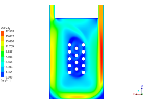

Figure 3- Velocity and Temperature contours. The left side shows high-speed gas entry, while the right side shows the temperature distribution on the tubes.
This finding supports the use of oxygen-enriched combustion in industrial designs. Increasing the amount of CO2 and H2O in the furnace is beneficial because these gases are good at absorbing and re-emitting radiation. The simulation proves that the physical arrangement of the tubes is critical. A bad arrangement blocks the radiation paths, while an optimized bundle, like the one simulated here, ensures uniform temperature and maximizes the chemical reaction rate for hydrogen production.
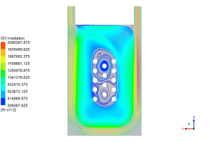
Figure 4- 2D Streamlines showing the path of the gas flow around the tube bundle. The lines show how gas circulates between the tubes.
Key Takeaways & FAQ
- Q: What is the main purpose of an SMR Furnace?
- A: It is used to produce Hydrogen and Syngas by reacting natural gas (methane) with steam at very high temperatures.
- Q: Why do we use the Discrete Ordinates (DO) Radiation model?
- A: In this simulation, radiation is the most important type of heat transfer. The DO model is the most accurate way to calculate how heat rays travel through the gas mixture.
- Q: Why is a structured mesh with 4 million elements necessary?
- A: Capturing the complex heat transfer and chemical species distribution requires a very fine grid. A lower quality mesh would give inaccurate temperature readings, making the design unsafe.


Reviews
There are no reviews yet.