
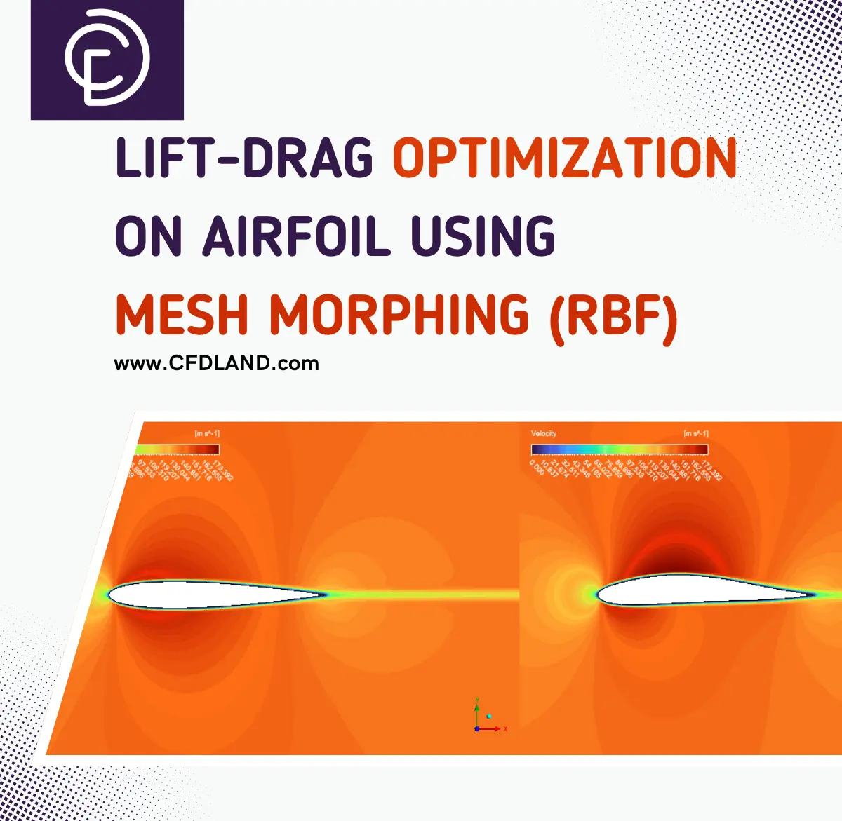

Aerodynamic optimization of airfoils is a critical challenge in aerospace engineering, as minor enhancements in lift-to-drag ratio can substantially increase aircraft efficiency and performance. Conventional optimization methods necessitate iterative cycles of geometric alteration, remeshing, and solution calculation—a protracted procedure that constrains design discovery. Radial Basis Function (RBF) mesh morphing provides a sophisticated method for facilitating dynamic alterations of airfoil shapes without necessitating complete domain remeshing throughout iterations. The combination of RBF morphing with optimization algorithms facilitates the effective study of design alternatives to ascertain airfoil designs that enhance lift while reducing drag under specified flying conditions. What we aim to do over base airfoil is to enhance lift-to-drag ratio using Mesh morphing technique in ANSYS Fluent.
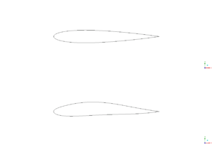
Figure 1: Base airfoil and proposed modification to enhance lift-to-drag ratio by Mesh morphing (RBF) technique
Simulation process
The optimization framework was constructed around a C-shaped computational domain extending in all directions to ensure far-field boundary independence. The baseline airfoil geometry served as the initial configuration, with the domain discretized using a high-quality structured grid featuring quadrilateral elements with appropriate clustering near the airfoil surface to resolve the boundary layer physics accurately. Flow conditions were set to a moderate subsonic regime with Mach number 0.4 (approximately 136 m/s), representing typical cruise conditions where both lift performance and drag reduction become critical design factors. The Spalart-Allmaras turbulence model was selected for its proven reliability in external aerodynamic applications with attached boundary layers and moderate pressure gradients, offering a good balance between computational cost and accuracy for airfoil analysis. Air was modeled as an ideal gas with standard atmospheric properties to properly account for compressibility.
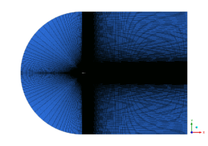
Figure 2: structured grid over airfoil domain for geometrical optimization using RBF mesh morphing
Post-processing
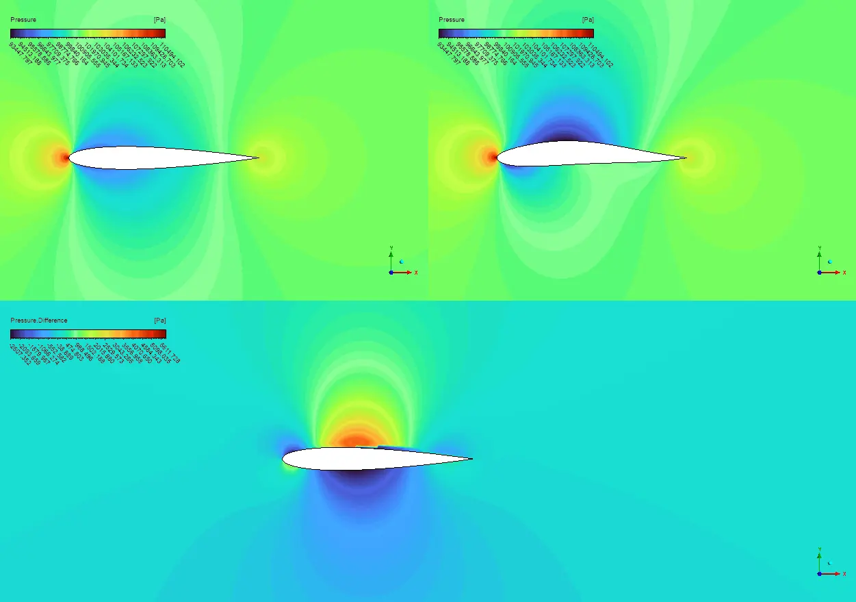
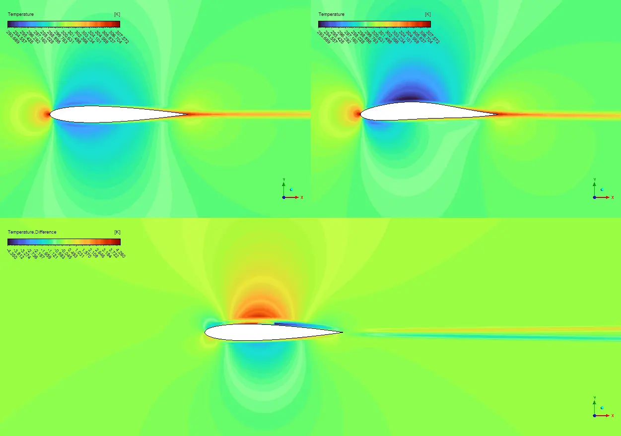
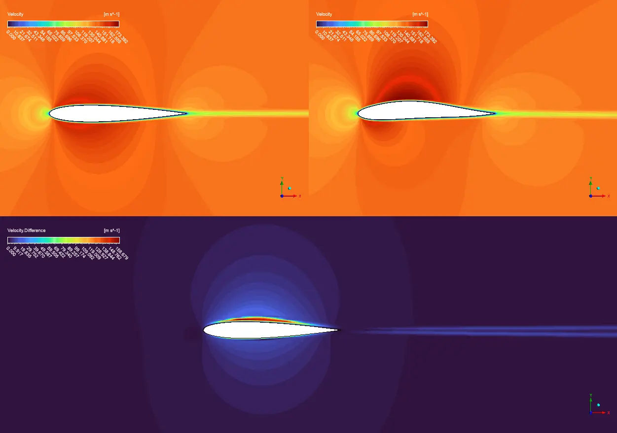
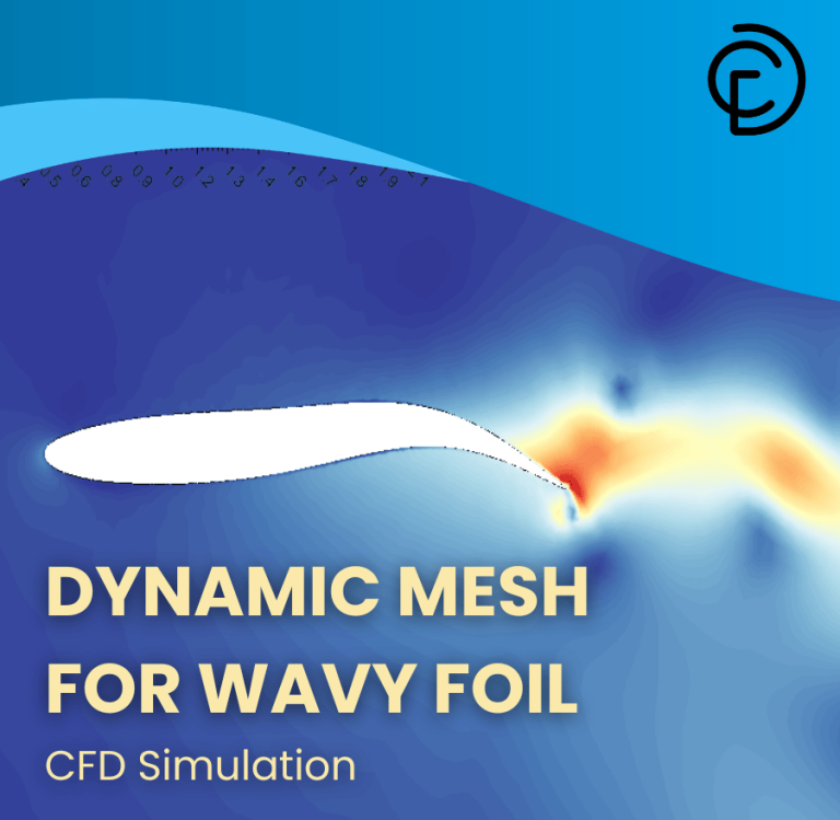
The optimization results proves a remarkable transformation in airfoil performance, with the lift coefficient increasing by over 400 times from virtually zero (CL = 0.00042) to a substantial value (CL = 0.17548) while incurring only a minimal 4.5% penalty in drag (CD increasing from 0.01139 to 0.01190). This dramatic improvement in lift-to-drag ratio is clearly visualized in the temperature contour plots, where the optimized airfoil exhibits a pronounced asymmetric temperature distribution with significantly higher temperatures above the airfoil (red-orange region) and lower temperatures below (blue-green region)—the classic signature of effective lift generation. The temperature difference plot further highlights this asymmetry, showing the concentrated high-temperature region above the airfoil that corresponds to the lower pressure zone responsible for lift production. The velocity contours provide additional insight into the optimization’s effectiveness, revealing substantially accelerated flow over the upper surface of the optimized airfoil (darker red region) compared to the more uniform flow field around the baseline geometry. This accelerated flow is directly responsible for generating the pressure differential that produces lift, according to Bernoulli’s principle. The velocity difference plot confirms these observations, showing the greatest flow modifications occurring near the leading edge and upper surface where the RBF morphing technique subtly adjusted the airfoil curvature to optimize pressure distribution.
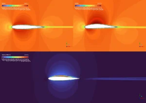

Figure 3: Lift-to-drag enhancement due to RBF mesh morphing implementation on subsonic flow over airfoil


Reviews
There are no reviews yet.