


A Transonic (Compressible) Flow Over 3D NACA0012 CFD simulation is critical for modern aircraft design. When a plane flies near the speed of sound (Mach 1), the airflow behaves in very complex ways, and strange effects like shock waves can appear. These effects dramatically increase drag and can affect the stability of the aircraft. By simulating a standard NACA0012 CFD profile in this speed range, engineers can validate their software and gain crucial insights into high-speed flight.
This type of advanced analysis builds on fundamental principles taught in our comprehensive ANSYS Fluent course for beginners, a Course that will equip you with the foundational skills for any CFD project.
Modeling the Transonic Airfoil Fluent Simulation
The simulation was performed in ANSYS Fluent using a 3D model of the NACA0012 airfoil. Modeling a Transonic Airfoil CFD problem correctly requires specific settings because the air’s properties change dramatically:* Compressible Flow: The density of the air is not constant. The ideal gas law was used to allow density to change with pressure and temperature.
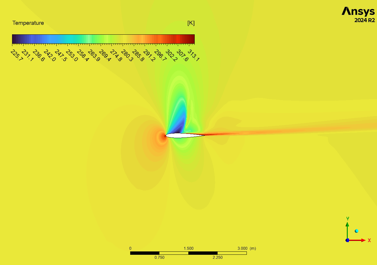
- Energy Equation: This must be enabled to account for the significant temperature changes that occur in high-speed flow.
- Solver: A density-based solver was used. This solver is specifically designed for high-speed, compressible flows and is essential for accurately capturing shock waves.
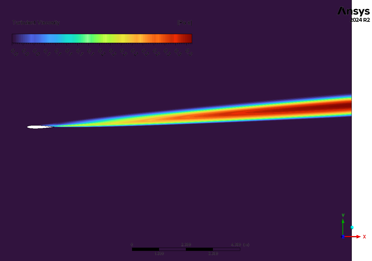
- Turbulence Model: The k-omega SST model was chosen because it provides highly accurate predictions for boundary layers and any potential flow separation, which is common in Airfoil CFD analyses.
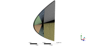
Figure 1: Structured grid over NACA0012 3D model
CFD Analysis: How Airfoil Curvature Creates a Shock Wave
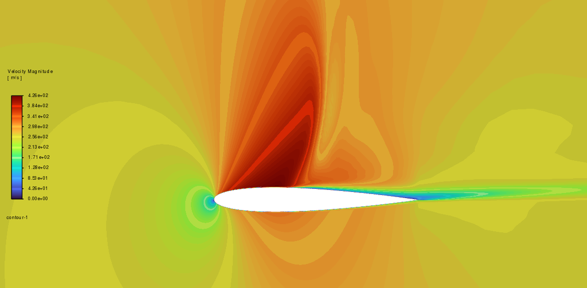
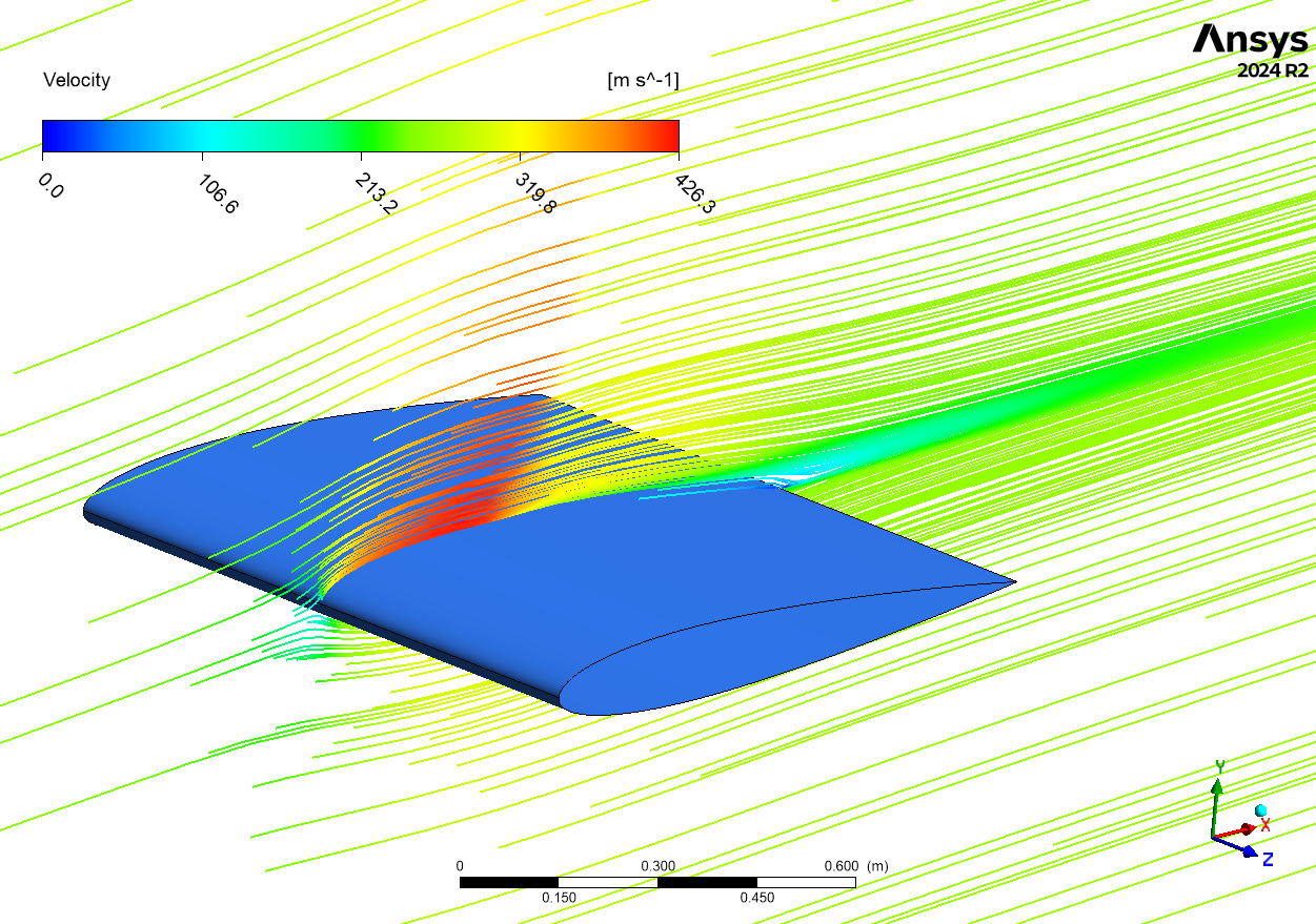
The simulation results provide a clear and fully substantiated story that begins with the combination of the airfoil’s curved upper surface and the high flight speed. This is the fundamental “cause” of all the complex physics. To get from the leading edge to the trailing edge, the air flowing over the curved top surface must travel a longer distance than the air flowing along the flatter bottom surface. To cover this longer distance in the same amount of time, the air on top must accelerate. The immediate “effect” of this acceleration is that the local flow speed on the upper surface breaks the sound barrier and becomes supersonic (Mach > 1), even though the aircraft itself is flying at a transonic speed (Mach < 1). The Mach number contour in Figure 2 is the perfect visual proof of this, showing a distinct pocket of high-speed, supersonic flow (in red) sitting on the top surface of the Airfoil Fluent model.
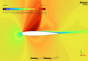
Figure 2: velocity distribution around NACA0012 3D model CFD Simulation
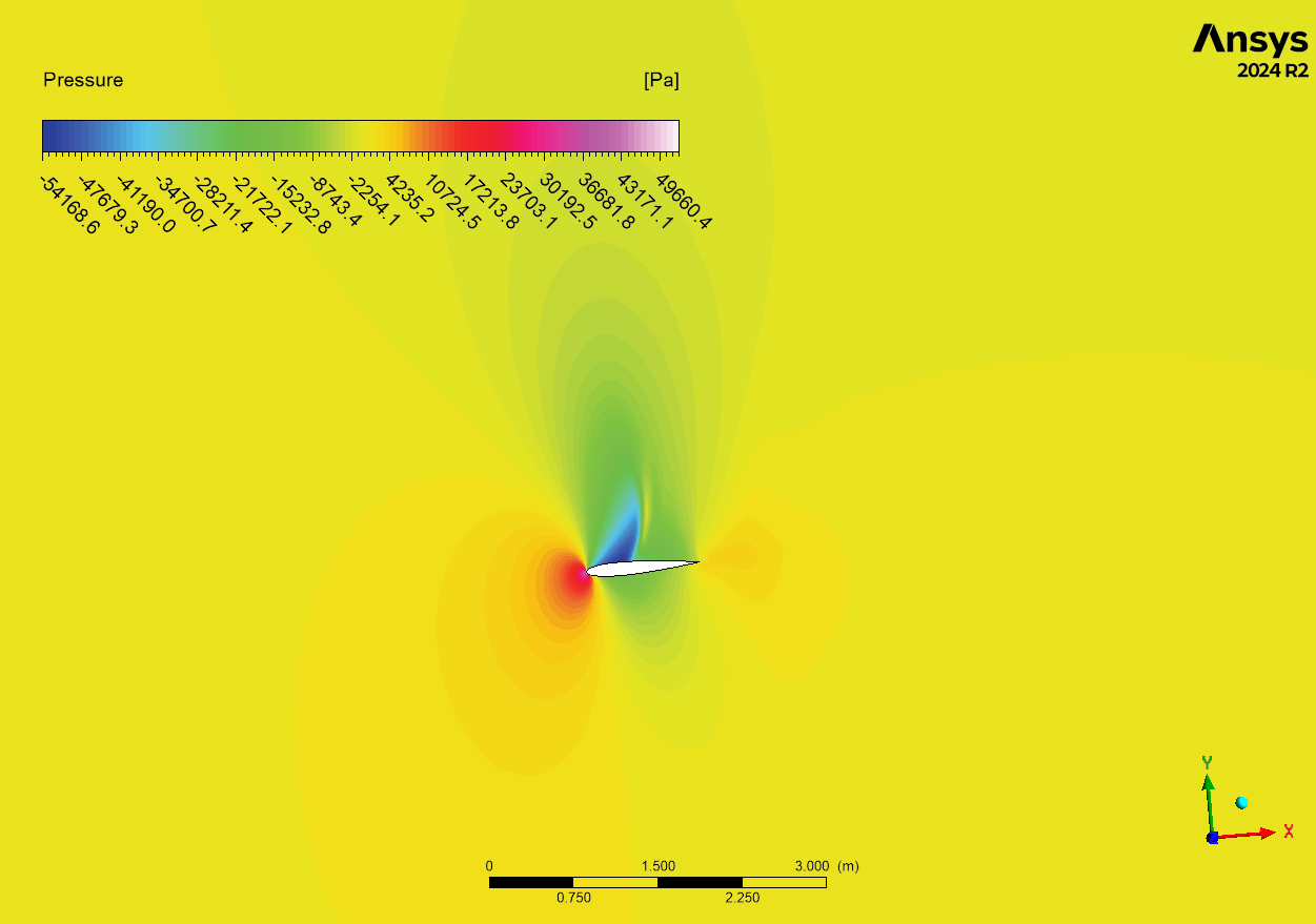
This pocket of supersonic flow is the “cause” of the next, most dramatic effect. As the supersonic flow moves toward the back of the airfoil, the shape of the wing becomes less curved, and the flow must slow down to rejoin the subsonic flow around it. Supersonic flow cannot slow down smoothly; it does so through an abrupt, almost instantaneous change called a shock wave. The “effect” of this is a thin, powerful shock wave that forms on the upper surface, acting like a sudden wall to the airflow. The pressure contour in Figure 3 provides definitive proof, showing a sharp, line-like jump in pressure exactly where the supersonic pocket ends. This shock wave is the primary source of a powerful new type of drag called “wave drag,” and it is the main reason why flying efficiently in the transonic regime is so challenging. The most significant achievement of this Transonic NACA0_012 CFD analysis is the clear demonstration of how the airfoil’s geometry at high speed (the cause) creates a local supersonic region that must terminate in a powerful shock wave (the effect). This validated CFD model allows engineers to accurately predict the location and strength of this shock wave, enabling them to design wings that minimize wave drag and improve the fuel efficiency and performance of high-speed aircraft.

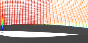
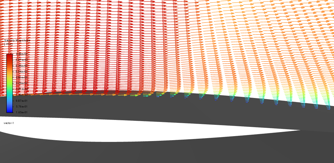
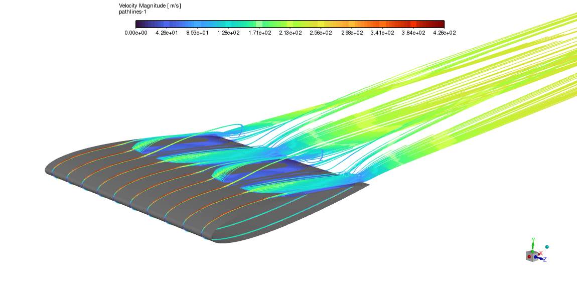
Figure 3: velocity a) pathlines b) vectors on suction side, showing flow separation
The formation of shock waves, the presence of a supersonic pocket, and the separation of flow all show how complicated transonic flow is. These things have a big effect on aerodynamic speed, making drag higher and possibly lowering lift.


Reviews
There are no reviews yet.