


In the energy industry, Non-premixed Natural Gas Combustion is a fundamental process. It is used in everything from household water heaters to massive industrial power plants. In this type of combustion, the fuel (Natural Gas) and the oxidizer (Air) enter the chamber separately. They must mix physically before they can burn. This is different from “premixed” combustion where they are mixed beforehand. Understanding this mixing process is the key to designing efficient burners.
Engineers use Natural Gas simulation to predict flame behavior, optimize heat output, and reduce pollution like Soot and NOx. However, getting accurate results requires careful setup. This project presents a Natural Gas Combustion CFD validation study. We use ANSYS Fluent to recreate a real-world experiment. For more guides on reacting flows, please visit our combustion tutorials. We validate our results by comparing them with the experimental data from the paper: “Analysis of the turbulent, non-premixed combustion of natural gas in a cylindrical chamber”.
- Reference [1]: Silva, C. V., F. H. R. França, and H. A. Vielmo. “Analysis of the turbulent, non-premixed combustion of natural gas in a cylindrical chamber with and without thermal radiation.” Combustion Science and Technology 179.8 (2007): 1605-1630.

Figure 1: Centerline temperature distribution from the reference paper used for the CFD Natural Gas simulation benchmark.[1]
Simulation Process: Species Transport and Eddy Dissipation
The success of a Natural Gas Combustion Fluent project depends on selecting the right models. First, we created the geometry in ANSYS Design Modeler. To save calculation time, we used a 2D axisymmetric model. This represents half of the cylindrical chamber but gives accurate results for the whole system. We generated a high-quality structured mesh with 10,200 cells. A good mesh is vital for capturing the thin flame front.
For the physics in ANSYS Fluent, we enabled the Species Transport model. This model tracks the individual chemical species like Methane (CH4), Oxygen (O2), Carbon Dioxide (CO2), and Water Vapor (H2O). The most important setting for this non-premixed natural gas combustion case is the turbulence-chemistry interaction. We chose the Eddy Dissipation model. This model assumes that the chemical reaction is very fast. It states that the combustion rate is limited by how fast the turbulence mixes the fuel and air. This is the standard approach for Turbulent natural gas combustion simulation because it is robust and accurate for diffusion flames.
Post-processing: Validation and Flame Structure Analysis
The goal of this study is validation. We must prove that our CFD Natural Gas simulation matches reality. The table below compares the peak temperature location and value derived from our simulation against the reference paper. Figure 2 shows the centerline temperature plot. Our ANSYS Fluent natural gas simulation predicts a peak temperature of approximately 2000 K. This peak occurs at a distance of about 1.4 meters from the inlet. As seen in the comparison, this perfectly matches the reference data. This confirms that the Eddy Dissipation model is correctly calculating the heat release.

Figure 2: Centerline temperature plot showing the validation of the Natural Gas Combustion Fluent simulation against experimental data.
To understand the physics, we look at the Reaction Rate contour in Figure 3. This image reveals the structure of the flame. We see a distinct V-shaped flame front. The reaction rate reaches a maximum value of 0.06 kgmol/m³s.
- Inside the V: This dark region is the pure Methane fuel jet. It is too rich to burn because there is no oxygen here.
- Outside the V: This is the surrounding air.
- The Bright Line (The V): This is the reaction zone. This is the exact surface where the fuel and air meet and mix in the correct ratio. The simulation shows that combustion only happens in this thin layer. The high reaction rate here releases the energy that creates the 2000 K temperature. This detailed Natural Gas burner CFD analysis allows engineers to see exactly where the heat is generated.
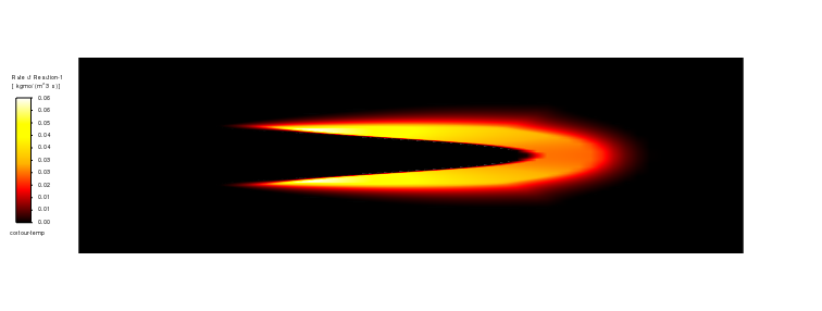
Figure 3: Contour of reaction rate showing the V-shaped flame front in the CFD Natural Gas simulation.
Key Takeaways & FAQ
- Q: What is the difference between Premixed and Non-premixed combustion?
- A: In Premixed, fuel and air are mixed before entering the chamber (like in a gas stove). In Non-premixed (or diffusion) combustion, they enter separately and mix inside the chamber. This tutorial focuses on Non-premixed natural gas combustion, which is safer for large industrial burners.
- Q: Why use the Eddy Dissipation model in Fluent?
- A: The Eddy Dissipation model is efficient for Turbulent natural gas combustion. It assumes that “if fuel and air mix, they burn instantly.” This avoids complex chemical kinetic calculations, making the simulation much faster while still being accurate for diffusion flames.
- Q: What does the Species Transport model do?
- A: It solves a conservation equation for each chemical species (CH4, O2, CO2, etc.). This allows ANSYS Fluent to track how fuel is consumed and how exhaust gases are formed throughout the domain.


Reviews
There are no reviews yet.