


Are you struggling with PEM fuel cell cooling challenges? Fuel cell stack cooling systems are critical for maintaining optimal performance in PEMFC (Proton Exchange Membrane Fuel Cell) applications. This ANSYS Fluent tutorial shows you how to set up a complete CFD simulation of a PEM fuel cell cooling system with realistic non-uniform heating conditions. Thermal management is one of the biggest challenges in fuel cell stack design, as excessive temperatures can severely damage the delicate membrane electrode assembly. Using ANSYS Fluent for PEMFC cooling simulation lets engineers test different cooling channel designs without expensive prototyping. The water cooling system commonly used in PEM fuel cell stacks must handle the heat generation that varies across different areas of the cell. This fuel cell CFD tutorial walks through the entire process of modeling coolant flow through a fuel cell cooling plate with non-uniform heat flux conditions. Whether you’re designing a small portable PEMFC system or a large fuel cell stack for vehicles, mastering cooling system simulation in ANSYS Fluent will help you create more efficient and reliable fuel cell thermal management solutions.
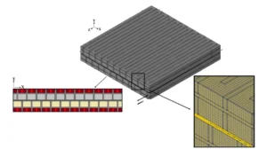
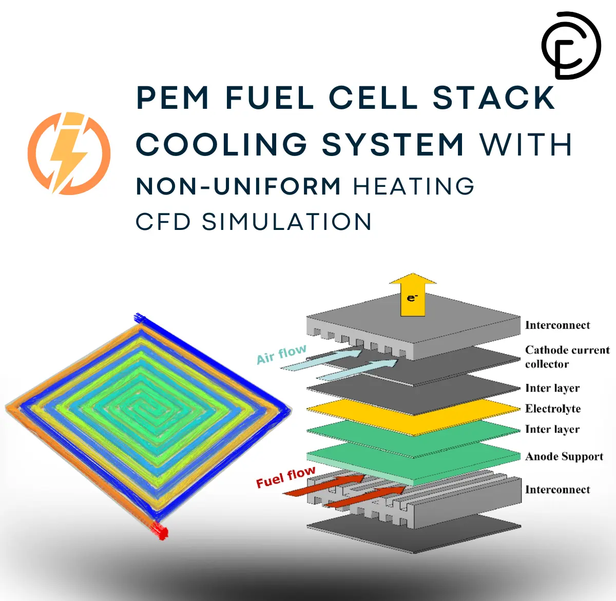
Figure 1: PEM Fuel Cell Stack Cooling System schematic
Simulation Process
For this CFD simulation, a detailed cooling channel was created using a structured grid comprising 5,334,816 cells to ensure high numerical accuracy. The channel material was specified as steel to accurately represent real-world PEMFC cooling system properties. A custom UDF (User-Defined Function) was implemented to apply non-uniform heat flux throughout the domain, simulating the realistic operating conditions of a PEM fuel cell stack where heat generation varies across active areas.
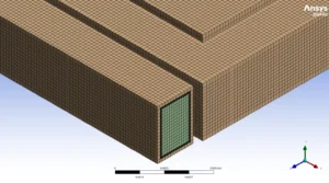
Figure 2: Structured grid produced for cooling system of PEMFC
Post-processing
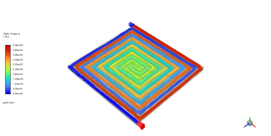
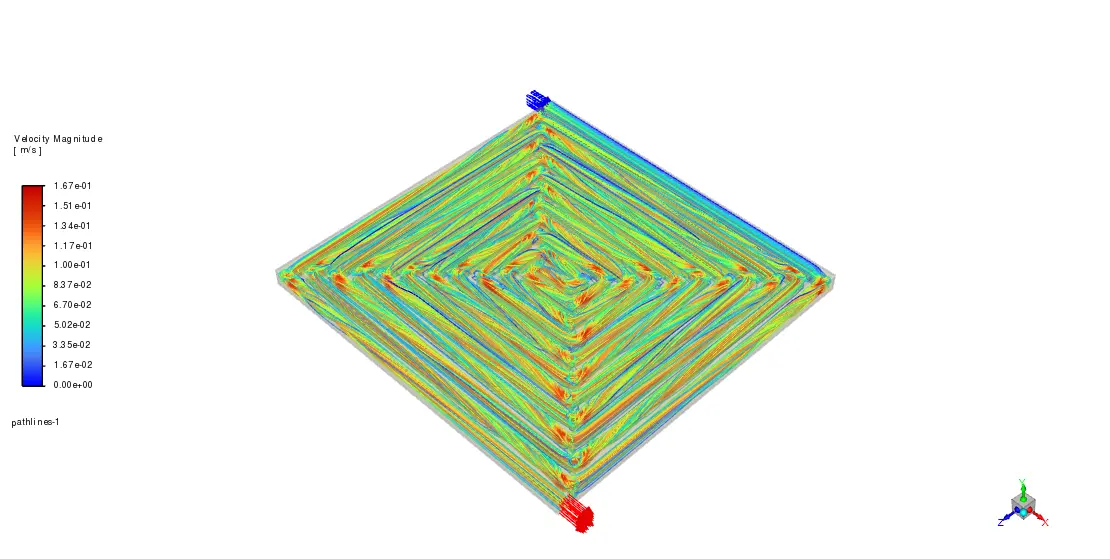
The velocity streamlines visualization reveals complex coolant flow patterns throughout the cooling channels. The color mapping shows velocities ranging from 0 m/s (blue) to 0.167 m/s (red), with most of the flow maintaining moderate velocities (yellow-green) around 0.08-0.12 m/s. The spiral flow pattern is clearly visible at each corner of the cooling system, which helps prevent stagnation zones where heat could build up. These vortices enhance heat transfer by promoting mixing and increasing the contact time between the coolant and channel walls. The highest velocities (red streamlines) occur primarily at the inner corners of the channel, which is exactly where we want increased flow to manage potential hotspots in the fuel cell stack.
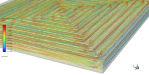
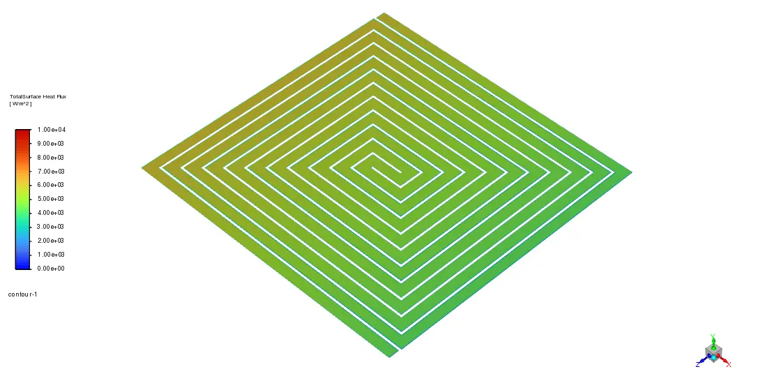
Figure 3: Stagnation regions in the cooling system corners
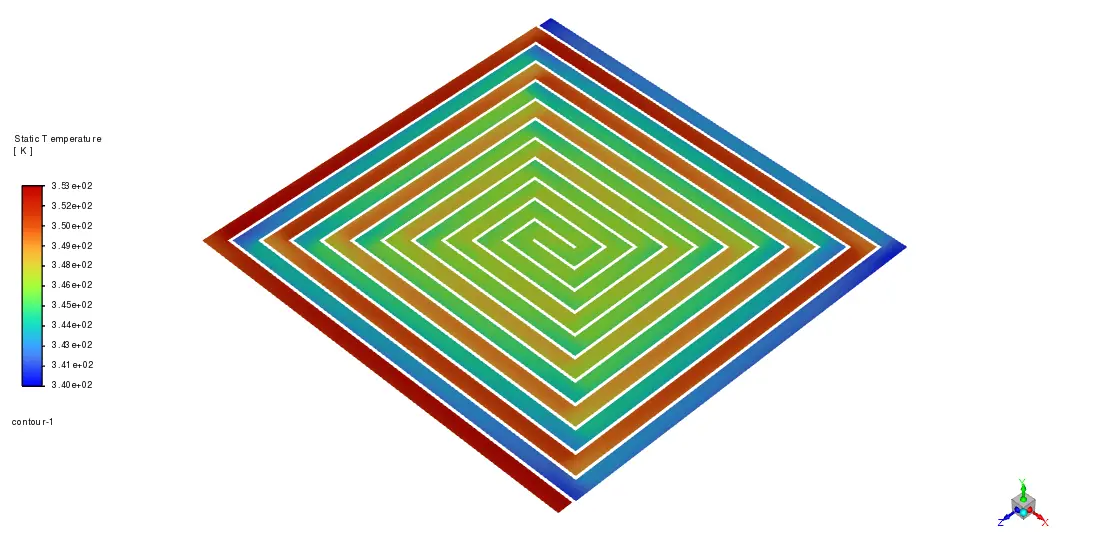
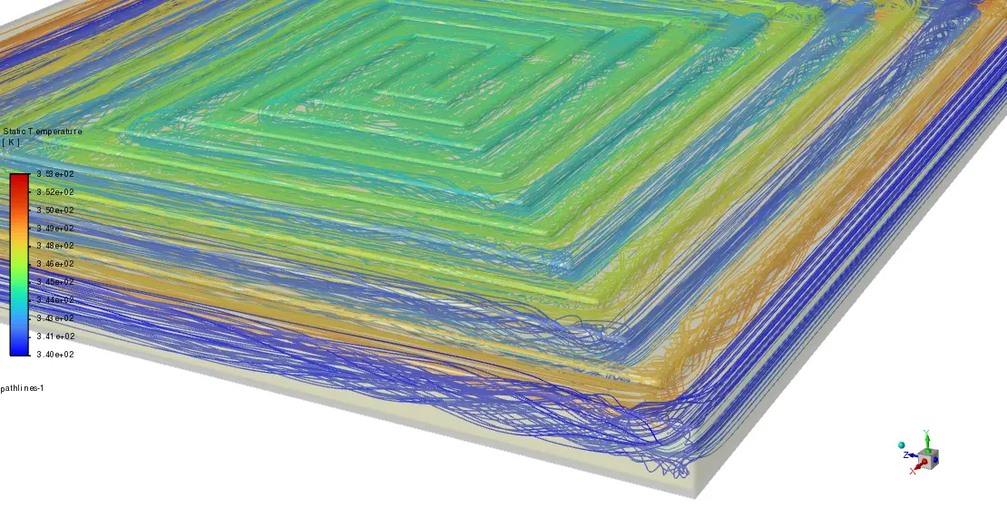
The temperature contour map shows how effectively the cooling system handles the non-uniform heating conditions. The coolant temperature gradually increases from the inlet (340K, blue) to around 350K at the outlet (red-orange regions). The spiral pattern in the temperature distribution matches the flow pattern, with cooler temperatures maintained throughout most of the channel. The concentric temperature rings indicate that the coolant flow effectively absorbs heat from the channel walls as it progresses through the system. This even temperature spread is crucial for PEMFC performance since it prevents thermal stress and degradation of membrane electrode assemblies. The maximum temperature difference of approximately 10K between inlet and outlet demonstrates that the cooling channel design efficiently manages heat removal while maintaining temperatures well below critical thresholds that could damage fuel cell components.
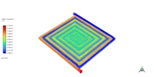
Figure 4: Temperature pattern inside PEMFC cooling system


Reviews
There are no reviews yet.