


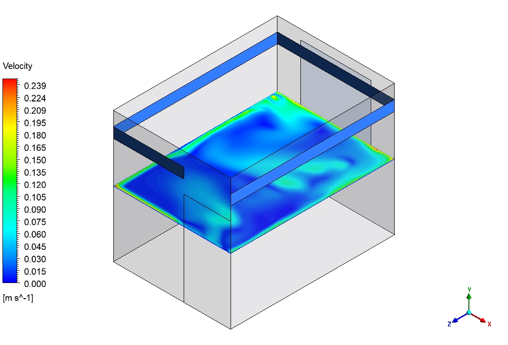


Keeping a room comfortable requires a good system to push fresh air around. This is called Active cooling. But how do engineers know if the air will reach every corner of the room before they build the building? They use a Room Ventilation By Cooling Duct CFD simulation. By creating a virtual room on a computer, we can see the invisible wind and make sure there are no dead, stuffy zones.
This report is a Room Ventilation By Cooling Duct fluent simulation tutorial. We will look at how cool air enters from a ceiling duct and travels through a standard room. We use the ANSYS Fluent software to calculate the complex math behind the airflow. By mastering this CFD Analysis of Room cooling, you can design better, more energy-efficient buildings. For more simple and powerful lessons on indoor airflow, please visit our HVAC tutorials.
Figure 1: The 3D model of the room with the inlet cooling duct and outlet vent.
Simulation Process: Mesh Setup
To begin this Room Ventilation By Cooling Duct ANSYS Fluent project, we built a 3D computer model of the room. A computer needs the room divided into thousands of tiny blocks to do the math. We used a high-quality “Structured Mesh” created by ANSYS ICEM (Figure 2). Structured meshes have neat, square rows, which make the airflow calculations much more accurate.
For the physics, we set the inlet cooling duct to blow air at a high speed of 5 m/s and a cold temperature of 290 K (17°C). Because the air is moving fast and swirling around objects, we turned on the k-epsilon (k-ε) turbulence model. This is the standard mathematical tool for Room HVAC fluent simulations because it is excellent at predicting how fast-moving air mixes with still air.
Figure 2: Grid generation by ANSYS ICEM for Room HVAC System CFD Analysis.
Post-processing: The Analytical Story of the High-Speed Jet
To truly understand this CFD Analysis of Room cooling, we must focus strictly on the mechanical force of the air. We are not looking at heat maps; we are looking at the engine that drives the comfort of the room. The “Cause” of all movement in this room is the cooling duct. It injects air at 5 m/s. Look at the Velocity Contour (Figure 3). You can clearly see a bright red streak shooting across the top of the room. This is the high-speed jet. This jet has high “momentum,” which means it is heavy and fast enough to punch right through the dead, still air already sitting in the room.
This jet creates a massive physical “Effect.” As the 5 m/s jet shoots across the ceiling, it acts like a vacuum on its edges, pulling the surrounding room air along with it. This is a physics concept called “entrainment.” When this powerful jet finally hits the opposite wall, it cannot go backward, and it cannot go through the wall. The wall forces the fast air to bend downwards toward the floor. It sweeps across the floor and then gets pulled back up toward the duct. This creates a giant, room-wide wheel of wind, known as a circulation loop or vortex.
The streamlines in our analysis prove this perfectly. You do not need a temperature map to know this room is being cooled properly; the velocity data alone proves it. Because the jet is strong enough (5 m/s) to hit the back wall and create this giant loop, we know that the 290 K fresh air is being violently mixed into every corner of the room. This Room Ventilation By Cooling Duct CFD simulation proves that the secret to good Active cooling is not just cold air, but giving that air enough velocity to create a mixing vortex.

Figure 3: Velocity contour showing the high-speed jet (red, 5 m/s) entering from the cooling duct and hitting the far wall to drive the room’s airflow.
Key Takeaways & FAQ
- Q: Why use the k-epsilon (k-ε) turbulence model?
- A: Because the air enters at a fast 5 m/s. The k-epsilon model is the best tool in ANSYS Fluent for calculating the chaotic, turbulent mixing that happens in large spaces like rooms.
- Q: What is the “engine” of the room’s ventilation?
- A: The high-speed jet. As seen in the velocity contour, the momentum of the jet from the cooling duct hits the far wall and creates a giant circulation loop.
- Q: What is entrainment?
- A: It is when the fast-moving jet of air grabs and pulls the slow, still air around it, forcing the entire room to mix together.





Reviews
There are no reviews yet.