


Sloshing is a complicated fluid behavior that is shown by the periodic motion of liquid-free surfaces inside containers that are only half full and are being energized from the exterior. This event has enormous engineering effects on many fields, such as maritime (LNG carriers, oil tankers), automotive (fuel tanks), aerospace (propellant tanks), and urban engineering (water storage facilities in seismic areas). Sloshing can create dynamic forces that can damage structures, make systems unstable, make noise, and lower total performance. For the best design and operating safety, it is important to understand the hydrodynamic properties of sloshing, such as resonance frequencies, damping effects, and impact loads. We will look at sloshing behavior using ANSYS Fluent with User-Defined Functions (UDFs) for Computational Fluid Dynamics (CFD) modeling in this tutorial. Our method is based on the study paper “Effect of viscosity on sloshing in a rectangular tank with intermediate liquid depth [1].” This paper tells us a lot about how fluid properties affect the free surface dynamics in partially filled rectangular containers when they are excited from the outside.
- Reference [1]: Jin, Xin, et al. “Effect of viscosity on sloshing in a rectangular tank with intermediate liquid depth.” Experimental Thermal and Fluid Science118 (2020): 110148.

Figure 1: Snapshots of the sloshing of glycerin at 35 °C under horizontal excitation [1]
Simulation process
A two-dimensional rectangle tank model made in ANSYS Design Modeler was used to study the sloshing effect. A fully structured mesh with 184,800 cells was used to divide the computational domain. The Volume of Fluid (VOF) multiphase model was used to track the contact between the air and water phases. The natural effects of buoyancy were taken into account by gravitational body forces. A User-Defined Function (UDF) was created to apply periodic sinusoidal motion to the tank walls, which matched the experimental conditions stated in the reference paper. This was done to simulate the external excitation. The UDF sets the tank’s oscillating motion by defining the amplitude, frequency, and direction parameters using the DEFINE_CG_MOTION macros. This lets the forcing function be accurately shown. For a quantitative analysis of the sloshing effects, two pressure sensors were placed in the bottom left corner of the tank, 0.03m and 0.07m above the bottom wall. This allowed for accurate measurements of the changing pressures during the sloshing phenomenon.
Post-processing
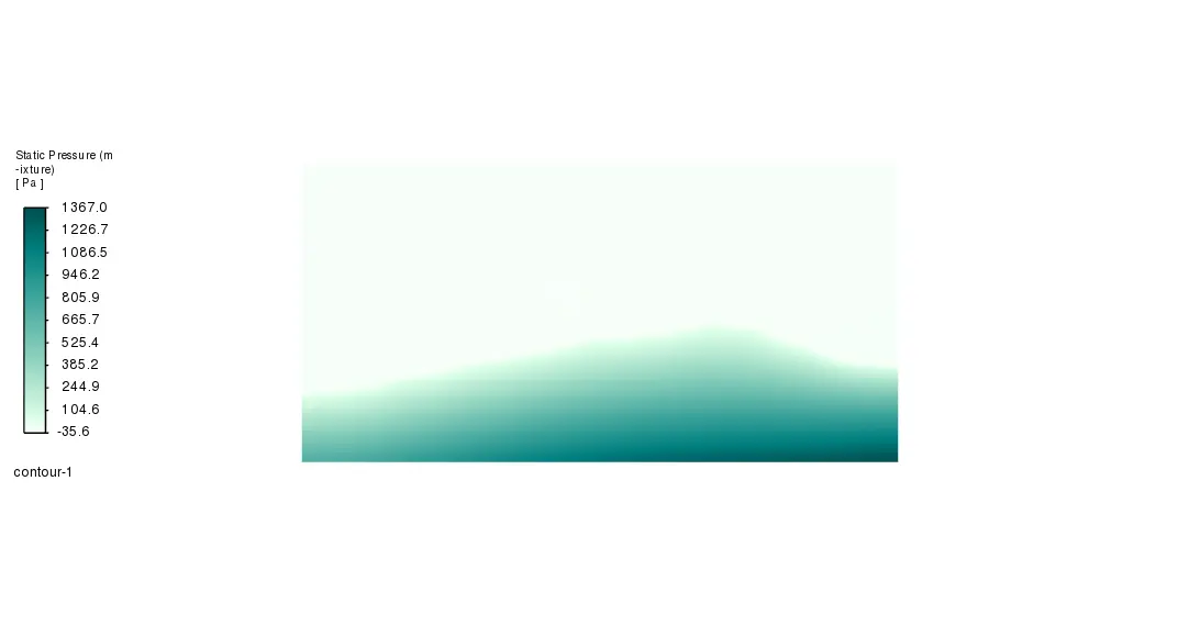
The pressure measurements from Sensor 1 (which is 0.03 m below the surface) show a clear periodic pattern that gets stronger over time. There are waves in the pressure that go from about 400 Pa to 1800 Pa. The waves get bigger over the first 3600 seconds before they hit a state that is almost steady. After the initial period of change, the pressure peaks become clearer and more regular, with steady high points around 1800 Pa happening at about the same time every time. This pattern shows that a resonant sloshing state has formed, which means that the forcing frequency is probably the same as or close to the system’s natural sloshing frequency. The sudden rises in pressure near the end of the simulation show that the fluid hit the tank wall severely.
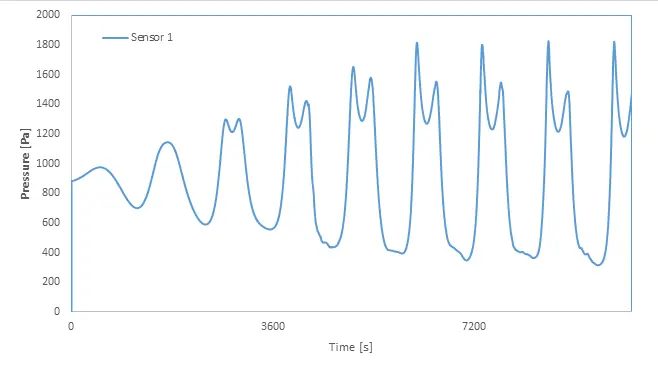
Figure 2: Pressure measured by sensor in Sloshing Tank CFD
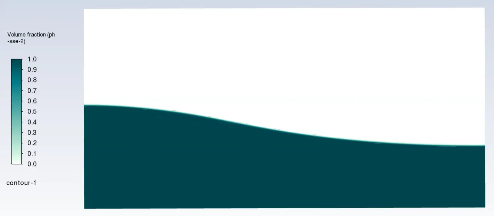
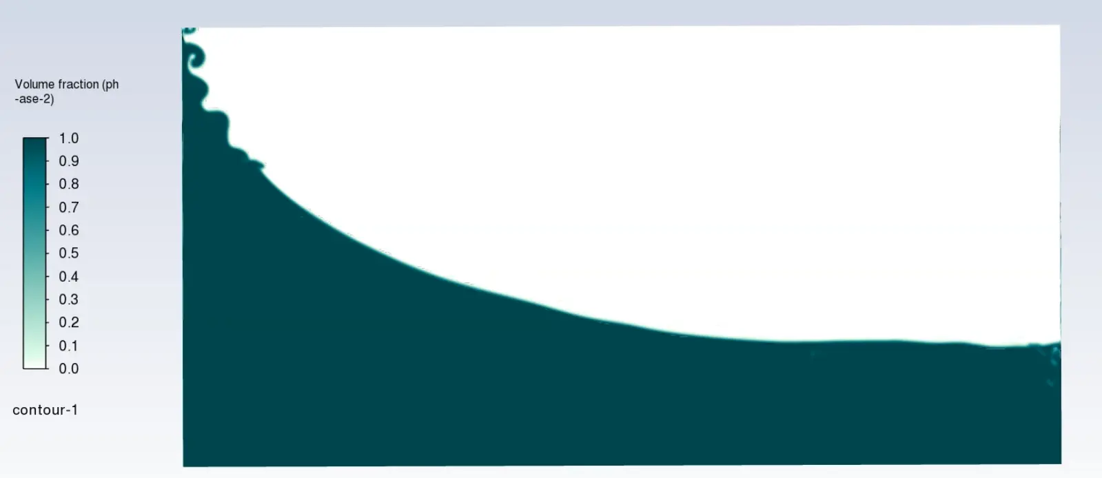
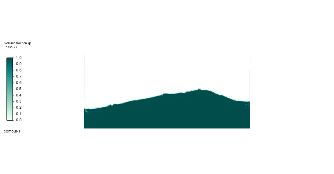
Figure 3: Wave distortion along the sloshing phenomenon inside the tank
The volume fraction contour plot shows that the free surface deforms a lot and waves form clearly where the liquid meets the air. The dark green area (volume fraction = 1.0) clearly shows the water phase. At the interface, there is a lot of distortion, with waves breaking and possible air entrainment, especially near the left wall, where small droplets and unstable surfaces can be seen. The free surface profile has a usual sloping pattern that is seen in sloshing behavior when there is forced excitation. The walls of the tank show the most displacement.


Reviews
There are no reviews yet.