


An ejector is a very clever pump that has no moving parts. It uses a fast-moving fluid to pull in and mix with a second, slower fluid. This is useful for everything from refrigeration to chemical processing. When the two fluids are different (like a liquid and a gas), it’s called a two-phase ejector. The biggest challenge is that the two fluids move at different speeds. This difference is called slip velocity, and it makes it very hard to guess how well the ejector will work. To solve this, we can use Computational Fluid Dynamics (CFD) with special instructions. We wrote a custom code called a User-Defined Function (UDF) to tell the computer exactly how to handle this slip velocity. Our goal is to perform a Two-phase Ejector CFD Validation by checking our simulation results against a trusted experimental study [1] to prove our model is accurate.
- Reference [1]: Yadav, Randheer L., and Ashwin W. Patwardhan. “Design aspects of ejectors: Effects of suction chamber geometry.” Chemical Engineering Science15 (2008): 3886-3897.
Figure 1: Schematic of the geometry used in the paper for the Ejector CFD Validation and simulation [1].
Simulation Process: Modeling Slip Velocity with a Custom User-Defined Function (UDF)
To create our Two-phase Ejector Fluent model, we first drew a 2D-axisymmetric shape of the ejector based on the paper’s dimensions. We then filled this shape with a neat, structured grid of little boxes to make our calculations very accurate. Because we had two phases mixing, we used the Mixture multiphase model. The most important step was creating a custom piece of code, a UDF, for the Slip Velocity CFD part of the problem. Instead of using Fluent’s built-in rules, our UDF gave a direct instruction for the slip velocity using the formula. This gives us much more control and allows us to match the real-world physics more closely.

Figure 2: The 2D geometry model used for the Two-phase Ejector CFD simulation in ANSYS Fluent.
Post-processing: Validating Performance and Visualizing the Flow
The simulation results reveal the powerful physics that make the ejector work. Figure 3 shows a powerful river of air, colored bright red, rocketing through the ejector’s throat. This jet reaches a peak speed of 46.5 m/s, creating an intense vacuum that pulls the secondary fluid into the device. This powerful suction is the heart of the ejector’s function. The simulation shows that this high-speed flow pulls in 0.00288 kg/s of the secondary fluid. This number, known as the entrainment rate, is the single most important measure of an ejector’s performance.
| Experimental Data | Current CFD Simulation | Error | |
| Entrainment rate | 0.00294 | 0.00288 | 2% |
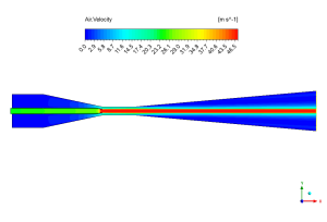
Figure 3: Air velocity contour from the Slip Velocity CFD analysis, showing the high-speed jet core responsible for suction.
Figure 4 gives us a map of the fluid’s journey, showing how the two streams mix together. The streamlines are squeezed tightly at the throat and then gracefully spread out in the diffuser section. This spreading out shows where the fast primary fluid shares its energy with the slower secondary fluid, causing them to mix completely. This detailed flow visualization confirms our model is behaving correctly. When we compare our calculated entrainment rate to the experimental paper’s value of 0.00294 kg/s, the difference is incredibly small. The most important achievement of this Two-phase Ejector Considering Slip Velocity CFD study is the incredibly low error of just 2% for the entrainment rate when compared to the experimental data [1]. This outstanding result proves that our custom UDF for modeling slip velocity works perfectly and gives engineers a highly reliable tool to design and optimize these complex devices with confidence.

Figure 4: Streamline distribution from the Two-phase Ejector Fluent simulation, visualizing the fluid paths and mixing process.


Reviews
There are no reviews yet.