

The interaction between a conductive fluid and a Uniform Magnetic Field is a cornerstone of Magnetohydrodynamics (MHD). This principle has profound importance in many advanced engineering fields, from controlling liquid metal flows in nuclear reactors to designing efficient MHD power generators. When a fluid like liquid metal moves through a magnetic field, a Lorentz force is created, which acts like an electromagnetic brake, fundamentally changing the flow’s structure. Accurately predicting this change is a critical engineering challenge. Therefore, performing a MHD Fluent Validation against proven experimental or numerical data is an essential step to ensure a CFD model is reliable and accurate. This project validates a Magnetic Field CFD simulation based on the high-impact research paper “Effect of Hartmann layer resolution for MHD flow in a straight, conducting duct at high Hartmann numbers” by Subramanian et al. [1].
- Reference [1]: Subramanian, Sharanya, et al. “Effect of Hartmann layer resolution for MHD flow in a straight, conducting duct at high Hartmann numbers.” Sadhana40 (2015): 851-861.

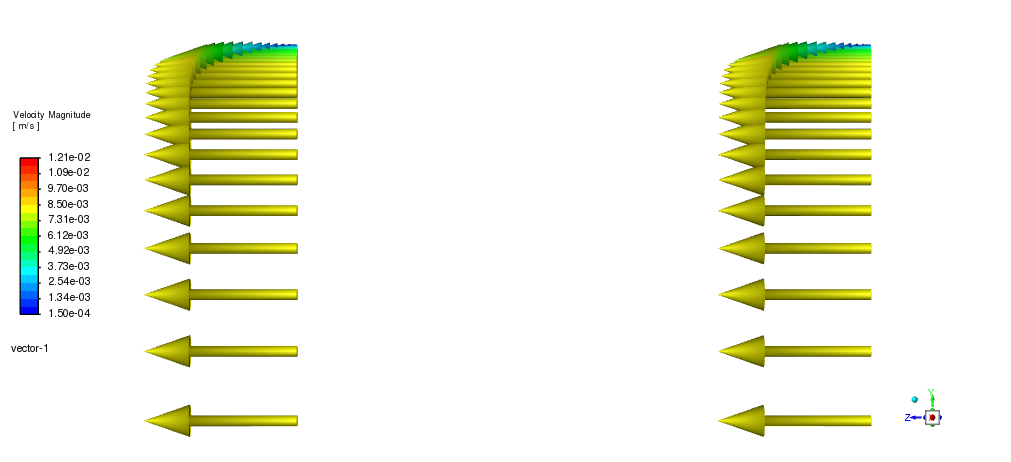
Figure 1: Uniform Magnetic Field CFD Simulation using the MHD module.
Simulation Process: Modeling the Uniform Magnetic Field CFD Simulation with the MHD Module
To replicate the conditions of the reference paper, two duct geometries were modeled: a square duct and a rectangular duct. A high-quality, structured mesh was created for the simulation, containing 2,040,000 hexagonal cells. As seen in Figure 2, the mesh is non-uniform; it is much finer near the walls and coarser in the center. This specific meshing strategy is critical for accurately resolving the thin, high-shear boundary layers, known as Hartmann layers, that form in CFD MHD flows.
Inside ANSYS Fluent, the simulation was set up using the built-in MHD module. We employed the Magnetic Induction and Electric Potential methods to solve the governing MHD equations. Because the Hartmann number was high relative to the Reynolds number, the laminar model was correctly chosen for the flow. A velocity of 0.01 m/s was set at the inlet, and the walls were defined with a no-slip condition.
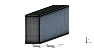
Figure 2: The structured, non-uniform grid refined near the walls to capture the Hartmann layer in the MHD Fluent Validation.
Post-processing: MHD Fluent Validation and Analysis of the Hartmann Layer
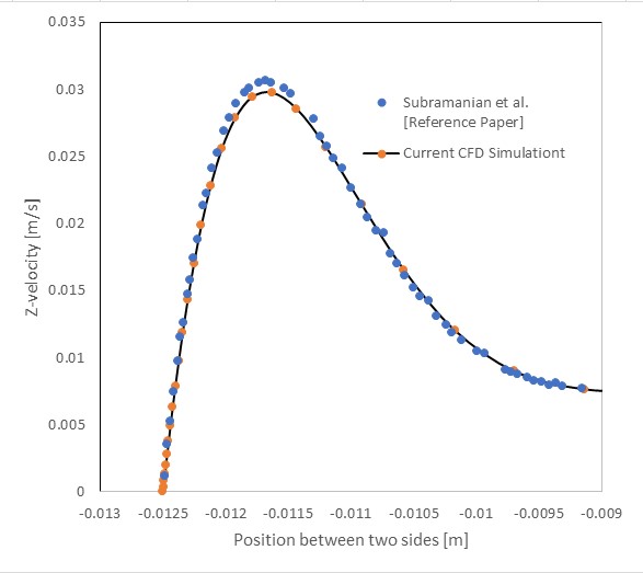
The primary goal of this simulation was validation, and the results show an outstanding agreement with the benchmark data. The validation graph in Figure 3 directly compares the velocity profile from our MHD CFD simulation (solid line) with the data points from the reference paper by Subramanian et al. [1]. The curves align almost perfectly across the entire width of the duct. The most significant achievement of this study is this successful validation, proving our model can accurately predict the flow physics, including the peak velocity of approximately 0.03 m/s in the duct’s core. This gives us high confidence in the simulation’s setup and its ability to produce reliable data.
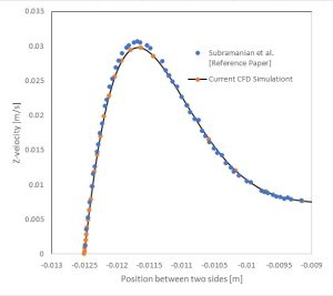
Figure 3: Validation graph comparing the MHD CFD simulation velocity profile (solid line) with the reference paper’s data [1].
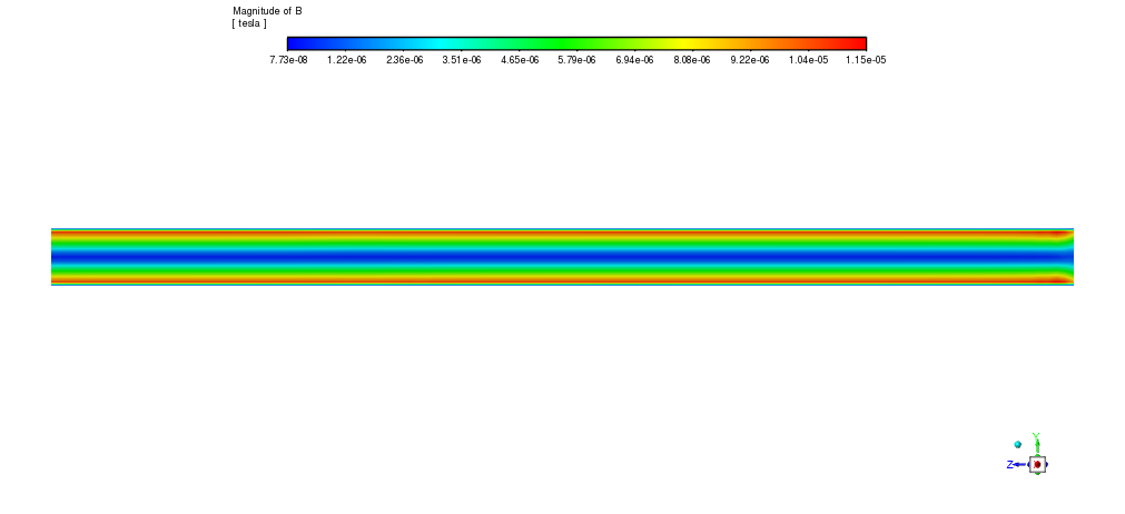
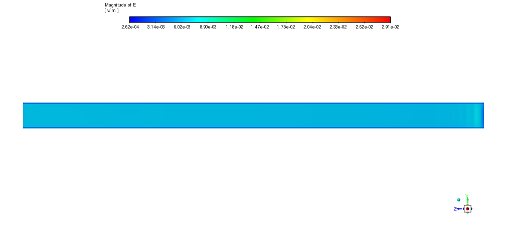
To understand why the velocity profile takes this unique shape, we must analyze the underlying electromagnetic fields shown in Figure 4. The applied Uniform Magnetic Field (B-field) interacts with the moving conductive fluid to induce an Electric Field (E-field). Together, these fields generate the Lorentz force. This force acts as a powerful brake, resisting the fluid’s motion. This braking is strongest near the walls and weaker in the center. The effect is a dramatic reshaping of the flow: the velocity profile is flattened in the core of the duct, and very steep velocity gradients are formed near the walls. This distinct phenomenon, perfectly captured in our Magnetic Field Fluent simulation, is the formation of the Hartmann layer. It is the direct physical cause for the M-shaped velocity profile seen in the validation graph, perfectly linking the electromagnetic cause to the fluid dynamic effect.


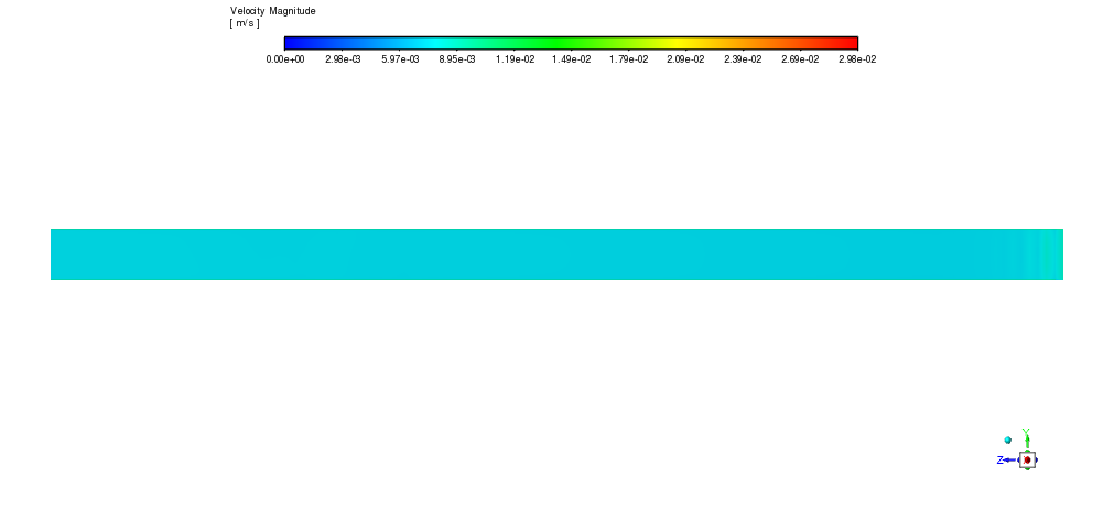
Figure 4: Scalar contours of a) Magnetic Field (B) and b) Electric Field (E) distribution from the Magnetic Field Fluent simulation.


Reviews
There are no reviews yet.