

With the increasing desire to use renewable energies, one of the hot topics in industry and university has become the use of wind turbines. The manufacturing and design of these turbines is a difficult and complex task that requires people with different expertise and methods. Among them, CFD is one of the most important methods used to design turbines and analyze them. In this article, we examine the importance of CFD simulations in turbine design and see the capabilities of ANSYS Fluent in this field.
What is a Wind Turbine?
As seen in the figure below, the wind turbine consists of several airfoil-shaped blades. Like the wings of an airplane, a lift is applied to these blades when they collide with the air flow, which causes them to rotate. The rotating blades are connected to the generator shaft, which produces electricity by rotating the shaft. The speed ratio of the blades to the shaft is controlled by a gearbox. The construction and production of these turbines is a difficult task that has complex processes.
These turbines work in different working conditions and wind speeds, which complicates their control, also in high wind speed, there is a possibility of breaking the blades, so engineers consider solutions for safety, such as using brakes to reduce the speed of the blades.
These turbines produce renewable energy and do not harm the environment, the only recorded case of their environmental problem is that they cause various animals such as birds to escape from the wind turbine area.

Several wind turbines on the coast
Analyzing Wind Turbines by CFD Simulations
We saw that different expertise and technologies are needed to design and build a turbine. In the meantime, turbine blades are designed with knowledge of fluid mechanics and airplanes, which are very suitable for study and verification through CFD simulation.
Due to the airfoil shape of turbine blades, similar to airplane wings, the phenomena and rules governing them are common. Engineers strive to increase the lift force while simultaneously reducing the drag force and preventing the phenomena of separation and stall. Currently, a lot of research is being conducted on wind turbine blades.
Due to the rotation of the blades around an axis in the turbine, each radius of the blade experiences a specific speed, which contrasts with airplanes, whose wings do not have rotational movement and experience uniform speed. Therefore, each section of the turbine blade is designed for a specific speed.
One way to optimize the turbine blade, increase the lift force, and decrease the drag force is to use flow controllers. These controllers come in different types. Some are small blades installed on the larger blade of the turbine, and others prevent the phenomenon of flow separation by blowing air on the surface of the turbine blade. The study and optimization of all flow controllers are currently being conducted with CFD simulations.
As seen in the previous figure, the turbines are placed together with different arrangements, which is called a wind farm. The air flow changes after passing through each turbine, and when it collides with the next turbines the air flow is weaker and due to asymmetry it may cause vibration. For this reason, the arrangement of turbines in a wind farm is important. CFD simulations are a very suitable option for optimizing the layout of turbines, although this simulation is very difficult and requires high computing power.
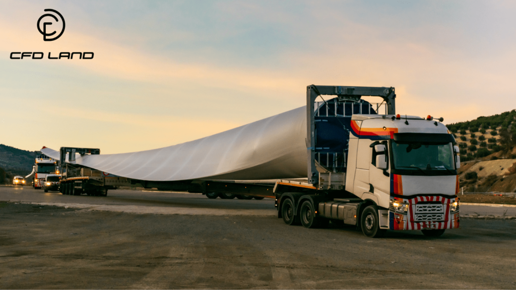
Turbine blades have an airfoil shape and are similar to airplane wings. In the picture, a turbine blade is being transported to the installation site.
Useful Tools and Features of ANSYS Fluent for Wind Turbine Simulations
ANSYS Fluent is a very powerful CFD simulation software that has shown its capabilities in various fields, including wind turbines. In the following, we will examine some of the capabilities of this software, which are used in simulations related to wind turbines.
Fluid-Structure Interaction (FSI)
The main reason for trying to reduce the drag on turbine blades is to prevent the failure of the turbine structure. Investigations related to the strength of the turbine structure are not possible without using the results of CFD simulations and the forces caused by fluid flow. The solution to this challenge is to use FSI simulations. In this simulation model, the ANSYS Fluent simulation results related to fluid flow are transferred to ANSYS Mechanical. After checking the stresses and deformations, the results are returned to Fluent, and this cycle is repeated regularly.
What is Fluid-Structure Interaction?
Multiple Reference Frames (MRF) and Single Reference Frames (SRF)
In these methods, the domain of the problem in which the turbine blade rotates is selected and the blade position is assumed to be constant and the blade speed is added to the air flow speed. This method greatly reduces the computational cost. In this method, a simple mesh is used, not a dynamic mesh. This method is suitable for simulating devices that have a rotating part, such as wind turbines and turbo machines. We have done many simulations on MRF and SRF fields in CFDLAND, which you can see in MRF CFD.
Dynamic Mesh
In some simulations, the turbine blade is required to move inside the domain. This work is possible by using dynamic mesh, which means mesh changes with the movement of the blade. This simulation model requires very high computing power. Many CFD simulations done with dynamic mesh can be seen in Dynamic Mesh CFD.
The capabilities of ANSYS Fluent in the field of wind turbine simulation are much more than what is stated here, this software is also very powerful in geometry modeling, meshing and post-processing.

One of the CFD simulations with ANSYS Fluent in the field of wind turbines carried out by CFDLAND is “ Leading Edge Tubercle On Wind Turbine Blade CFD Simulation“.
Conclusion
In conclusion, CFD is a suitable method to investigate the effect of air flow on wind turbines. Among the different CFD software, ANSYS Fluent is the right choice for wind turbine simulations, which has all the details and features required for these simulations.
Wind turbine simulations are complex and require high expertise. Our experts at CFDLAND are highly skilled in wind turbine simulations. Trust us and Order ANSYS CFD projects.