

In many engineering problems, we analyze how a fluid and a solid object affect each other. To answer what is fluid-structure interaction, it is the direct study of this physical relationship. It is an important concept in modern engineering that helps us understand the link between flow structure interaction and solid movement. In an FSI problem, the fluid creates pressure and forces that can cause the structure to move or change shape. Consequently, the structure’s new movement alters the path of the fluid flow. Engineers also refer to this continuous cycle as Fluid Solid Interaction.
A Fluid Structure Interaction CFD simulation combines two fields of physics: fluid dynamics and structural mechanics. Instead of assuming that the solid walls are perfectly fixed, an FSI simulation calculates both the fluid flow and the structural response together. You need this approach when a structure is flexible enough that fluid forces cause it to deform, bend, or vibrate significantly. For example, a standard CFD analysis works perfectly for water flowing in a rigid pipe. However, if the pipe is flexible and vibrates due to the flow, we must run an 2-way ANSYS FSI simulation to get realistic results. This method is critical for designing safe bridges that resist strong winds and efficient artificial heart valves. These are just a few examples. Honestly, despite the fact that we cover all aspects of FSI simulation in this blog, still each case study requires special considerations and settings to achieve successful status. This is why we highly recommend visiting our our detailed Fluid Structure Interaction (FSI) Tutorials & Examples .
Figure 1: Various applications of Fluid-Structure Interaction (FSI) simulation, showing fluid-solid coupling in offshore structures, oil tankers, wind turbines, and pump impellers.
Governing Equations and Mathematical Formulation of FSI
For better comprehension of Fluid-structure interaction modeling, we must look at the mathematical physics. A complete FSI system contains three distinct parts. These are the fluid domain, the solid domain, and the shared boundary between them. Software solves specific equations to model each part accurately.
First and foremost, the fluid behavior follows the Navier-Stokes equations. These formulas calculate the speed, direction, and pressure of the fluid. For a standard incompressible flow, we write the mass conservation (continuity) and momentum equations as:
- Continuity: \nabla \cdot v_f = 0
- Momentum: \rho_f (\frac{\partial v_f}{\partial t} + v_f \cdot \nabla v_f) = -\nabla p + \mu_f \nabla^2 v_f + f_f
In these equations, vf is the fluid velocity, p is the pressure, ρf is the fluid density, and μf is the dynamic viscosity.
The solid object follows the equations of structural dynamics. These equations explain how the solid bends, moves, or deforms when outside forces push it. We express this physical behavior using Newton’s second law for continuous solid materials:
- Solid Dynamics: \rho_s \frac{\partial^2 d_s}{\partial t^2} = \nabla \cdot \sigma_s + f_s
Here, ds represents the physical displacement of the solid, ρs is the solid density, and σs is the internal stress tensor.
The most critical part of the simulation is the shared boundary. We call this the fluid-solid interface. At this location, the mathematical solver must apply two strict rules to ensure proper fluid-solid coupling. First, the fluid and the solid must move together without separating. Second, the forces must balance perfectly.
- Kinematic Condition: The velocity of the fluid must match the moving speed of the solid surface ( v_f = \frac{\partial d_s}{\partial t} ).
- Dynamic Condition: The physical forces from the fluid pressure must equal the stress forces acting on the solid structure ( \sigma_f \cdot n = \sigma_s \cdot n , where n is the normal vector).
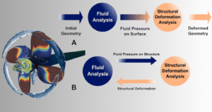
Figure 2: Numerical simulation of fluid-structure interaction shows how fluid flow and solid deformation are connected.
FSI Modeling Approaches in ANSYS
When you perform a fluid structure interaction ANSYS simulation, Three main methods are provided by the software, and each is suited for specific physics problems. As a CFD engineer, we ought to select the approach that accurately captures the real-world behavior without adding unnecessary complexity. These primary modeling approaches are Rigid Body FSI, One-Way FSI, and Two-Way FSI.
- The simplest method is Rigid Body FSI. This approach is used when the solid structure moves inside the fluid but does not bend or deform. The analysis focuses entirely on the physical motion of the object. A floating boat on water is a perfect example of this behavior.The boat moves up and down (heave) or tilts (pitch and roll) due to waves, but the boat’s hull itself is considered rigid. This is indeed a type of dynamic mesh 6DOF simulation, where the computational grid adapts to the body’s six degrees of freedom. Researchers often study many dynamic mesh 6DOF tutorials to learn how to implement this powerful technique.


Figure 3: Rigid Body FSI analysis of a floating boat, calculated using the 6DOF dynamic mesh method in ANSYS.
- The second method is One-Way FSI. This technique is applied when fluid flow causes structural deformation, but that deformation is too small to change the fluid flow path. First, the fluid simulation is run to calculate the pressure and thermal loads on the structure. Next, these specific loads are transferred directly to a structural solver. The final stress and deformation are then calculated by the software. The simulation data travels in only one direction, from the fluid to the solid structure. This highly efficient approach is commonly chosen for projects like calculating wind stress on a tall building.
- Two-Way FSI must be used for problems involving large structural changes that alter the fluid flow. This is the most detailed and computationally heavy FSI simulation in ANSYS Fluent. In this advanced method, information is constantly exchanged between the fluid and structural solvers. The fluid forces physically deform the structure. Consequently, the new structural shape changes the fluid flow behavior. This mathematical cycle is repeated at every single time step, which creates a fully coupled system. This detailed method is necessary for studying complex phenomena like a fluttering flag, a vibrating aircraft wing, or the motion of an artificial heart valve.
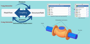
Figure 4: One-way vs. two-way fluid-structure interaction: one-way affects only the solid, two-way affects both fluid and solid.
One-Way FSI Implementation
A One-Way FSI analysis, often called one-way coupling, is a powerful and efficient method for many engineering applications. The core principle is simple: the fluid flow applies physical loads to the structure, but the resulting structural deformation is considered too small to change the fluid flow behavior. Because of this physical assumption, a static data transfer of information from the fluid domain to the structural domain is permitted. Within the software workspace, engineers use two main workflows to achieve this: the highly flexible ANSYS Workbench FSI approach and the specialized Intrinsic 1-way module within ANSYS Fluent.
The ANSYS Workbench Workflow
The most common method for a fluid solid interaction Fluent simulation is linking separate analysis systems in ANSYS Workbench. This workflow is highly versatile. It allows users to combine the best features of both the CFD and Finite Element Analysis (FEA) solvers. First, a complete CFD analysis is performed in Fluent to solve the fluid dynamics. Once the fluid solution converges, a detailed map of all fluid-induced loads on the structure is generated. These specific thermal and structural loads include:
- Pressure (Force Vector)
- Surface Temperature
- Volumetric Temperature
- Heat Transfer Coefficient (HTC)
- Heat Flux

Figure 3: Standard One-Way FSI workflow in ANSYS Workbench, directly linking Fluent CFD results to the ANSYS Mechanical solver.
The data transfer within the Workbench environment is seamless. A direct link can be created from the Fluent Solution cell to the Mechanical Setup cell, which automatically imports the fluid loads. For more advanced cases, the External Data module is utilized. This specific tool allows engineers to import load data from text files and apply it to the structural model. Once inside ANSYS Mechanical, proper FSI mesh interface setup is required. You must apply these imported fluid forces as physical boundary conditions to the relevant surfaces at the fluid-solid interface. Finally, the structural solver calculates the exact stress, strain, and deformation.

Figure 4: Using the External Data module in ANSYS for a complex One-Way FSI load transfer
The Intrinsic 1-Way FSI Module in Fluent
For certain problems, a more integrated approach is offered: the Intrinsic 1-way module. This advanced technique performs the fluid structure interaction analysis entirely within a single Fluent session. For this to work correctly, your model must contain both fluid and solid cell zones that share a perfectly conformal mesh at their interface. Fluent solves the fluid dynamics first. Then, its built-in FEA solver is used to compute the structural deformation based on the fluid forces. This intrinsic solver primarily uses a Linear Elasticity model, which aligns perfectly with the small-deformation assumption of one-way FSI.

Figure 5: Enabling the intrinsic One-Way FSI method using the Structural Model panel directly within ANSYS Fluent.
The primary options for the structural material model are:
- Linear Elasticity: This is the most common choice for one-way FSI. It assumes a linear relationship between the applied force and the resulting displacement. This specific model is appropriate only when the structure’s stress is expected to remain below the material’s yield strength.
- Nonlinear Elasticity: This advanced model is used to simulate large deformations where the geometry changes significantly. It accounts for geometric nonlinearity using advanced formulas like the neo-Hookean hyper-elastic model. While large displacements are handled, the simulation is still considered one-way if these solid changes do not influence the fluid flow.
It is important to understand that this intrinsic structural model is configured and solved entirely inside the Fluent interface. Therefore, it is not compatible with the standard Workbench system-linking workflow. The choice between the Workbench and intrinsic methods largely depends on the complexity of the required structural analysis.
Technical Note on Mapping: A critical technical step in the Workbench workflow is transferring loads between two completely different meshes. The surface mesh of the fluid model and the structural model rarely match perfectly. To solve this complex issue, ANSYS uses great mapping and interpolation methods. These mathematical algorithms intelligently transfer the pressure and thermal data from the fluid mesh nodes directly to the solid mesh nodes. This ensures that the total force and energy are perfectly conserved. This precise mapping is vital for reliable results in any fluid structure interaction ANSYS simulation.
Two-Way FSI with System Coupling
When the interaction between the fluid and solid is strong enough that the structural deformation significantly alters the fluid flow, a high-fidelity Two-Way FSI simulation is necessary. This advanced approach captures the continuous, dynamic feedback loop between the two physics. In the ANSYS software, this complex co-simulation is managed directly by the ANSYS Fluent System Coupling module. This powerful tool orchestrates the physical data exchange between ANSYS Fluent and ANSYS Mechanical, creating a strongly coupled fluid-structure interaction.
Principle of Bidirectional Iterative Coupling
Ideally, fluid and structural equations are assembled into a single monolithic system and solved simultaneously. However, in practical engineering, a partitioned approach is more effective. In this method, specialized solvers for CFD and FEA talk to each other. This is exactly what fluid-solid coupling facilitates.
The simulation progresses through a continuous loop that ensures physical equilibrium at every single time step. This bidirectional data exchange forms the core of the analysis:
- Fluid Load Calculation: ANSYS Fluent solves the fluid dynamics equations for a single coupling iteration. The exact pressure and viscous forces are calculated on the shared fluid-solid interface.
- Data Transfer (Forces): The physical force data is received by the System Coupling module. It is then mapped accurately onto the structural mesh in ANSYS Mechanical.
- Structural Deformation: ANSYS Mechanical solves for the structural response. The software calculates the resulting displacements and internal physical stresses based on the applied fluid loads.
- Data Transfer (Displacements): The calculated nodal displacements are received by the System Coupling tool. These are mapped back onto the fluid interface mesh in Fluent.
- Fluid Domain Update via Dynamic Mesh: This step is critical. To account for the new structural position, the physical mesh must be updated by ANSYS Fluent. This process is handled by the Dynamic Mesh model, which mathematically deforms the fluid volume to match the new solid boundary.
- Convergence Loop: With the newly updated mesh geometry, Fluent re-solves the fluid flow. This entire mathematical loop is called a coupling iteration. It is repeated several times within a single time step until the exchanged data perfectly converges.

Figure 6: The coupling diagram shows the iterative data exchange between fluid flow and transient structural domains to achieve convergence in two-way fluid-solid coupling.
Setting Up a Two-Way FSI in ANSYS Workbench
The entire workflow for a fluid structure interaction ANSYS co-simulation is managed logically within the Workbench project schematic.
- Project Schematic Setup: The foundation is built by dragging the required systems onto the project page. A Fluid Flow (Fluent) system and a Transient Structural system are utilized. Next, a System Coupling system is added. The fluid and structural systems are then linked to it to create the necessary connections for data exchange.

Figure 7: A typical Two-Way FSI project schematic in ANSYS Workbench. It connects the fluid and structural solvers through the System Coupling module.
- Individual Physics Setup: Each solver must be configured with its own physics and correctly identify the exact interface.
- In ANSYS Mechanical, material properties are defined, and structural constraints are applied. A Named Selection must be created for the surface interacting with the fluid, identifying it as the “Fluid-Solid Interface”.
- In ANSYS Fluent, fluid properties and boundaries are set. Most importantly, the Dynamic Mesh model is enabled. For the interface wall, you must specify that its physical motion is driven by System Coupling. The Double Precision solver is highly recommended for FSI cases to maintain numerical accuracy.
- System Coupling Configuration: The System Coupling interface serves as the master control for the simulation. Here, engineers define:
- Data Transfers: Specific transfers are created, such as linking the Force variable from Fluent to Mechanical, and the Displacement variable back to Fluent.
- Analysis Controls: The total simulation End Time and Step Size are set.
- Convergence Criteria: The minimum and maximum coupling iterations per time step are defined. The solution only proceeds to the next time step after all convergence targets are met.
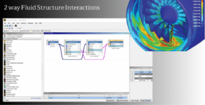
Figure 8: ANSYS Workbench interface showing fluid-structure interaction setup with Fluent and Mechanical solvers
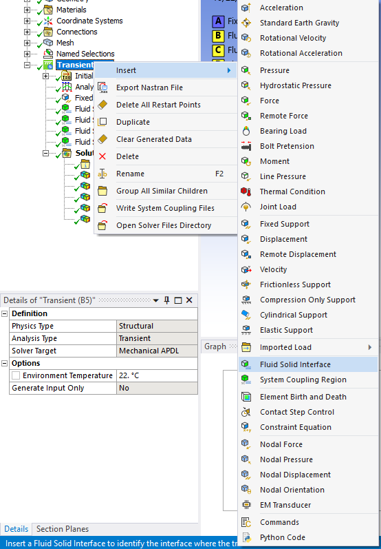
Figure 9: Defining fluid-solid interfaces in ANSYS ensures proper force and motion transfer between fluid and structural environments.
Understanding the Three Levels of Iteration
A transient FSI simulation in ANSYS Fluent is computationally heavy. This is because fluid-structure interaction modeling involves a nested hierarchy of three different iteration levels.

Figure 10: The three levels of iterations in a transient Two-Way FSI simulation. The solver and coupling loops must converge for each individual time step.
- Time Steps: This is the outermost loop. It advances the simulation through physical time from start to finish.
- Coupling Iterations: This is the middle loop managed by System Coupling. It ensures the fluid and solid domains reach equilibrium within each time step.
- Solver Iterations: These are the innermost loops. They represent the standard mathematical iterations performed by Fluent and Mechanical to solve their equations within a single coupling iteration.
This fully-coupled approach is the gold standard for accurately simulating complex phenomena. The power of two-way fluid-solid coupling allows engineers to tackle some of the most challenging multiphysics problems across various industries.

Figure 11: Applications of Two-Way FSI simulations, including aeroacoustics of a helical wind turbine, vibration of a column under wave loading, fuel sloshing in a tanker, and biomechanics of the human eye.
Advanced FSI Configuration
Moving beyond the basic setup, a deep understanding of advanced configuration settings is required to truly learn a Two-Way FSI simulation. This section covers the best practices, critical solver settings, and troubleshooting techniques. These formal steps are essential for achieving an accurate and perfectly converged fluid structure interaction simulation.
The System Coupling Control Center
The System Coupling interface acts as the central hub where the entire co-simulation procedure is defined. While the individual physics are physically set up in Fluent and Mechanical, their interaction is completely controlled by System Coupling. This is a core part of solving fluid-structure interaction multiphysics. Key settings include:
- Analysis Type: This mode can be set to either transient or steady-state.
- Time Control: The total End Time and the Time Step Size are defined here. It is crucial to understand that these master settings override any time step controls specified within ANSYS Fluent or Mechanical.
- Coupling Iterations: The Minimum and Maximum number of coupling iterations are set for each time step. The simulation proceeds to the next time step only after the data transfers have converged or the maximum iteration count is reached.
- Data Transfers: The exact data being exchanged is explicitly defined here (for example, linking Force from Fluent to Mechanical, and Displacement from Mechanical to Fluent). Convergence targets and relaxation factors are also applied to stabilize the mathematical solution.

Figure 10: The System Coupling user interface acts as the central control panel. It manages time steps, coupling iterations, and data transfers between the fluid and structural solvers.
Essential Solver Settings for Coupled Analysis
Several strict settings within the individual solvers must be configured correctly for a successful co-simulation. Beginners often wonder how to set up FSI in ANSYS Fluent to avoid solver crashes. The following rules apply:
- Solver Precision: It is a strong rule to run the ANSYS Fluent solver in Double Precision for all FSI cases. The fluid dynamics are highly sensitive to small changes in boundary position. Therefore, higher numerical precision is utilized by the software to guarantee stability and accuracy.
- Understanding Force Transfer: The physical force transferred from Fluent is calculated based on the gauge pressure relative to a Reference Pressure. By default, this reference pressure is zero. Because of this, only gauge pressure and viscous forces are sent. For applications with significant ambient pressures (like a deep subsea pipe), the Reference Pressure must be adjusted. This ensures the correct absolute pressure load is transferred to the structural model.
- Solver Iterations per Coupling Step: The Max Iterations/Time Step setting in Fluent’s Run Calculation panel takes on a new meaning during FSI. It now defines the maximum number of CFD solver iterations performed for each coupling iteration, not for the entire time step.


Figure 11: ANSYS Fluent coupling systems in action. The iterative data transfer ensures accurate force mapping and resulting structural deformation in ANSYS Mechanical.
Conclusion
This complete guide explains the essential workflows for modeling fluid-structure interaction within the ANSYS ecosystem. Both basic and advanced methods are fully covered here. We moved from the highly efficient One-Way FSI approach for static load transfers to the advanced Two-Way FSI method for fully dynamic problems. The System Coupling module and the Dynamic Mesh model are mathematically required for these complex setups. Accurate and robust simulations are achieved when you apply the correct solver configurations. When engineers master these powerful software tools, they easily solve the hardest multiphysics problems. These technical challenges range from aerospace wing flutter to biomechanical blood flows.
Highly specialized FSI simulations often require expert guidance. Professional assistance is provided by our company to ensure optimal and fast results. Our dedicated team of FSI specialists offers complete engineering consultation and custom problem-solving. You can directly order your project to our CFD Experts.