

The overall heat transfer coefficient is one of the most important concepts in thermal engineering. Whether you’re designing heat exchangers, analyzing building insulation, or optimizing cooling systems, understanding the heat transfer coefficient is essential for success. This comprehensive guide explains everything about the overall heat transfer coefficient in simple terms. First, we’ll cover the overall heat transfer coefficient definition and heat transfer coefficient units. Then, we’ll explore the overall heat transfer coefficient formula for different applications including pipes, walls, and heat exchangers.
Moreover, you’ll learn how to calculate heat transfer coefficient values for real systems. We’ll provide overall heat transfer coefficient tables with typical values for water, air, and other fluids. Additionally, we’ll show practical examples and common mistakes to avoid.
At CFDLand, we specialize in Heat Transfer CFD Simulation that helps engineers analyze and optimize thermal performance. Furthermore, this guide connects theory with practical applications, including how to use overall heat transfer coefficient in ANSYS Fluent.
By the end of this article, you’ll master the overall heat transfer coefficient concept and apply it confidently in your projects. Let’s start with the basics!

Figure 1: Some CFD Heat Transfer Analysis done by CFDLAND using ANSYS Fluent
What is Overall Heat Transfer Coefficient?
The overall heat transfer coefficient is a fundamental parameter that measures how well heat transfers through a system. Simply put, the overall heat transfer coefficient (commonly written as U value or just U) tells us the total heat transfer rate through materials and fluids.
Furthermore, the overall heat transfer coefficient definition includes all resistances to heat flow. These resistances come from:
- Convection on the hot side
- Conduction through solid materials
- Convection on the cold side
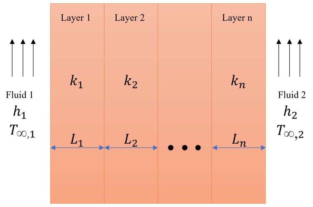
Figure 2: Thermal resistance in a medium
Why is Heat Transfer Coefficient Important?
The heat transfer coefficient helps engineers design efficient thermal systems. Moreover, understanding the overall heat transfer coefficient is crucial for:
- Sizing heat exchangers correctly
- Calculating heat loss in buildings
- Designing cooling systems
- Optimizing industrial processes
In heat exchangers, the overall heat transfer coefficient combines the convection heat transfer coefficient of both fluids plus the conduction resistance of the pipe wall. Additionally, any fouling or scaling affects the U value heat transfer significantly.
The Physical Meaning
Think of the overall heat transfer coefficient like this: it’s similar to electrical conductance. In other words, a higher heat transfer coefficient means heat flows more easily (like high electrical conductance). Conversely, a lower U value means more resistance to heat flow (better insulation).
The overall heat transfer coefficient answers this question: How much heat transfers per square meter for each degree of temperature difference?
Overall Heat Transfer Coefficient Formula and Calculation
The overall heat transfer coefficient formula is the foundation for all thermal calculations. Simply put, this formula helps us calculate how much heat transfers through any system.
Basic Heat Transfer Equation
The fundamental overall heat transfer coefficient formula is:
Q = U × A × ΔT
Where:
- Q = Heat transfer rate (Watts)
- U = Overall heat transfer coefficient (W/m²·K)
- A = Heat transfer area (m²)
- ΔT = Temperature difference (K or °C)
Moreover, this simple equation shows that heat transfer depends on three factors: the heat transfer coefficient, the area, and the temperature difference. Double the U value and you double the heat transfer rate!
How to Calculate Overall Heat Transfer Coefficient
For a flat wall with convection on both sides, the overall heat transfer coefficient calculation uses this formula:
1/U = 1/h₁ + L/k + 1/h₂
Where:
- h₁ = Convection heat transfer coefficient on hot side (W/m²·K)
- h₂ = Convection heat transfer coefficient on cold side (W/m²·K)
- L = Wall thickness (m)
- k = Thermal conductivity of wall material (W/m·K)
Furthermore, each term represents a resistance to heat flow:
- 1/h₁ = Convection resistance on side 1
- L/k = Conduction resistance through wall
- 1/h₂ = Convection resistance on side 2
Thermal Equivalent Circuit
The thermal resistance concept makes heat transfer coefficient calculations much easier to understand. Simply put, heat flow is like electrical current, and temperature difference is like voltage.
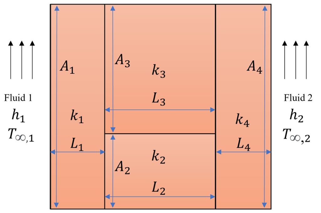
Figure 3. Heat transfer between two fluids through a composite wall. Note that A1 and A4 are equal, and L2 and L3 are equal.
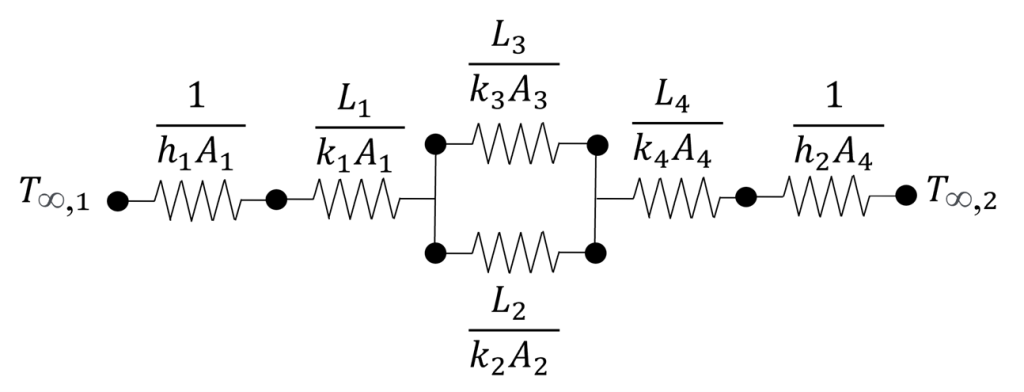
Figure 4. The thermal equivalent circuit of the system is in Figure 2.
Just like electrical circuits, thermal resistances add up:
- R_conv1 = 1/(h₁A) – Convection resistance on hot side
- R_cond = L/(kA) – Conduction resistance through wall
- R_conv2 = 1/(h₂A) – Convection resistance on cold side
Therefore, If thermal resistances are in series, the total thermal resistance is:
For Series (most common):
R_total = R₁ + R₂ + R₃ + …
For Parallel paths:
1/R_total = 1/R₁ + 1/R₂ + 1/R₃ + …
Moreover, parallel heat paths occur in:
- Composite walls with different materials side by side
- Finned surfaces where heat flows through fins AND base
- Windows with frame and glass areas
The overall heat transfer coefficient relates to total resistance:
U = 1/(A × R_total)
Calculating Overall Heat Transfer Coefficient for Parallel Paths
When heat paths are parallel, the overall heat transfer coefficient calculation becomes:
U_total × A_total = U₁ × A₁ + U₂ × A₂ + …
For example, a wall with a window:
- Wall area: A₁ with U₁ = 2 W/m²·K
- Window area: A₂ with U₂ = 5 W/m²·K
The average overall heat transfer coefficient is: U_avg = (U₁ × A₁ + U₂ × A₂)/(A₁ + A₂)
Remember: parallel paths increase the overall heat transfer coefficient because heat finds the easiest route.
Practical Example
Let’s calculate the overall heat transfer coefficient for a simple wall:
- Hot side: h₁ = 100 W/m²·K (convection heat transfer coefficient for air)
- Wall: L = 0.1 m, k = 1 W/m·K (brick)
- Cold side: h₂ = 25 W/m²·K (natural convection)
Using the overall heat transfer coefficient formula: 1/U = 1/100 + 0.1/1 + 1/25 = 0.01 + 0.1 + 0.04 = 0.15
Therefore: U = 6.67 W/m²·K
Additionally, this shows that the wall conduction (0.1) is the biggest resistance. The heat transfer coefficient is limited by the largest thermal resistance.
Overall Heat Transfer Coefficient for Different Geometries
The overall heat transfer coefficient changes with geometry. Moreover, cylindrical shapes like pipes and tubes require different formulas than flat walls. Let’s explore the most common geometries in detail.
Overall Heat Transfer Coefficient: Cylindrical Tubes
Pipes and tubes are everywhere in heat exchangers. Furthermore, the overall heat transfer coefficient cylindrical formula accounts for the curved surface area that changes with radius.
For cylindrical tubes, the heat transfer coefficient calculation becomes:
1/U = 1/h_i + (r_o/r_i) × (1/h_i) + (r_o × ln(r_o/r_i))/k + 1/h_o
Where:
- h_i = Inner convection heat transfer coefficient (W/m²·K)
- h_o = Outer convection heat transfer coefficient (W/m²·K)
- r_i = Inner radius (m)
- r_o = Outer radius (m)
- k = Thermal conductivity of pipe material (W/m·K)
At CFDLand, we’ve conducted a comprehensive Flow Over Heated Cylinder CFD Simulation + Analytical Solution Validation that demonstrates:
- ANSYS Fluent prediction of heat transfer coefficient around cylinder circumference
- Comparison between CFD results and analytical correlations
- Local Nusselt number distribution showing maximum heat transfer at stagnation point
- Validation of overall heat transfer coefficient calculations
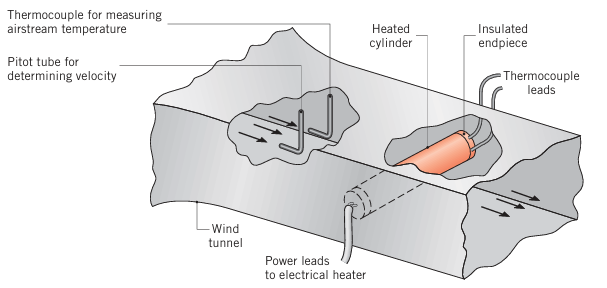
Figure 5: Flow over a tube CFD analysis – Validation against analytical solution by means of ANSYS Fluent
Moreover, this study shows how CFD simulation captures the complex heat transfer patterns that simple correlations miss. The heat transfer coefficient varies significantly around the cylinder, being highest at the stagnation point and lowest in the wake region.
Simplified Formula for Thin Tubes
For thin-walled tubes where the thickness is much smaller than the radius, we can simplify the overall heat transfer coefficient formula:
1/U ≈ 1/h_i + t/k + 1/h_o
Where t = tube wall thickness (m)
This simplification works when (r_o – r_i) << r_i. Additionally, this formula looks similar to the flat wall formula, making calculations easier.
Heat Exchanger Geometries
Heat exchangers use various geometries. Moreover, each geometry affects the overall heat transfer coefficient differently:
Shell and Tube Heat Exchangers
The heat exchanger overall heat transfer coefficient depends on:
- Tube arrangement (triangular, square)
- Number of tube passes
- Baffle design
- Flow patterns (counterflow, parallel flow)
For shell and tube designs, the overall heat transfer coefficient typically ranges:
- U = 150-1200 W/m²·K for liquid-liquid
- U = 15-70 W/m²·K for gas-gas
- U = 150-500 W/m²·K for gas-liquid
Plate Heat Exchangers
Plate heat exchangers achieve higher heat transfer coefficient values due to:
- Thinner walls
- Corrugated surfaces creating turbulence
- Larger surface area per volume
Typical overall heat transfer coefficient for plate exchangers:
- U = 3000-7000 W/m²·K for water-water
- U = 500-2000 W/m²·K for oil-water
Finned Surfaces
Fins increase the overall heat transfer coefficient by adding surface area. Furthermore, the fin efficiency must be considered:
1/U_finned = 1/(η_f × h_f × A_f/A_total) + R_wall + 1/h_other
Where:
- η_f = Fin efficiency (0 to 1)
- A_f = Fin area
- A_total = Total area (fins + base)
Remember: fins help most when one side has a low convection heat transfer coefficient, like air cooling.
Overall heat transfer coefficient units
The units of overall heat transfer coefficient expressed in various systems:
- International System of Unit (SI): Watts per square meter per Kelvin (W/(m2.K))
- Imperial Units (British Engineering Unit): BTU per hour per square foot per degree Fahrenheit (BTU/(h.ft2.°F))
- Metric Unit: Joule per second per square meter per Kelvin (J/(s.m2.K)) or Watt per square meter per degree Celsius (W/(m2.°C))
- International Unit: Kilocalorie (IT) per hour per square meter per degree Celsius (kcal/(h.m2.°C))
Heat Transfer Coefficient Values and Tables
Here are typical U values for common applications:
TABLE 2 Representative Values of the overall heat transfer coefficient, from fundamentals of heat and mass transfer by Frank P. Incropera et al.
| Application | Fluids | Overall Heat Transfer Coefficient (W/m²·K) | U Value (BTU/hr·ft²·°F) |
|---|---|---|---|
| Condensers | Steam to water | 1000-6000 | 175-1050 |
| Heat Exchangers | Water to water | 800-1500 | 140-265 |
| Heat Exchangers | Oil to water | 100-350 | 20-60 |
| Air Coolers | Water to air | 10-40 | 2-7 |
| Boilers | Hot gases to water | 10-50 | 2-9 |
| Building Walls | Air to air | 1-5 | 0.2-0.9 |
Typical values of the overall heat-transfer coefficient for various types of heat exchanger are given in Table 3. The reference values of Table 3 have been taken from Coulson & Richardson’s Chemical Engineering Vol. 6, 2nd Edition & 3rd Edition, R K Sinnot.
Table 3. Typical overall heat transfer coefficients
|
Shell and tube exchangers |
|||||
| Hot fluid | Cold fluid | U (W/(m2.K)) | |||
| Heat exchangers
Water Organic solvents Light oils Heavy oils Gases Coolers Organic solvents Light oils Heavy oils Gases Organic solvents Water Gases Heaters Steam Steam Steam Steam Steam Dowtherm Dowtherm Flue gases Flue Condensers Aqueous vapours Organic vapours Organics (some non-condensables) Vacuum condensers Vaporisers Steam Steam Steam |
Water Organic solvents Light oils Heavy oils Gases
Water Water Water Water Brine Brine Brine
Water Organic solvents Light oils Heavy oils Gases Heavy oils Gases Steam Hydrocarbon vapours
Water Water Water Water
Aqueous solutions Light organics Heavy organics |
800-1500 100-300 100-400 50-300 10-50
250-750 350_ 900 60-300 20-300 150-500 600-1200 15-250
1500-4000 500-1000 300_ 900 60-450 30-300 50-300 20-200 30-100 30-100
1000-1500 700-1000 500-700 200-500
1000-1500 900-1200 600_ 900 |
|||
|
Air-cooled exchangers |
|||||
| Process fluid | |||||
| Water
Light organics Heavy organics Gases, 5-10 bar 10-30 bar Condensing hydrocarbons |
300—450
300-700 50-150 50-100 100-300 300-600 |
||||
|
Immersed coils |
|||||
| Coil | Pool | ||||
| Natural circulation Steam
Steam Steam Water Water Agitated Steam Steam Steam Water Water |
Dilute aqueous solutions Light oils Heavy oils Aqueous solutions Light oils Dilute aqueous solutions Light oils Heavy oils Aqueous solutions Light oils |
500-1000 200-300 70-150 200-500 100-150 800-1500 300-500 200-400 400-700 200-300 |
|||
|
Jacketed vessels |
|||||
| Jacket | Vessel | ||||
| Steam
Steam Water Water |
Dilute aqueous solutions
Light organics Dilute aqueous solutions Light organics |
500-700
250-500 200-500 200-300 |
|||
|
Gasketed-plate exchangers |
|||||
| Hot fluid | Cold fluid | ||||
| Light organic
Light organic Viscous organic Light organic Viscous organic Light organic Viscous organic Condensing steam Condensing steam Process water Process water Dilute aqueous solutions Condensing steam |
Light organic
Viscous organic Viscous organic Process water Process water Cooling water Cooling water Light organic Viscous organic Process water Cooling water Cooling water Process water |
2500-5000
250-500 100-200 2500-3500 250-500 2000-4500 250-450 2500-3500 250-500 5000-7500 5000-7000 5000-7000 3500-4500 |
|||
Heat Transfer Coefficient of Water
Water is the most common fluid in heat transfer. Furthermore, the heat transfer coefficient of water varies significantly with flow conditions:
Natural Convection in Water:
- Horizontal plates: h = 100-600 W/m²·K
- Vertical plates: h = 200-1000 W/m²·K
Forced Convection in Water:
- Low velocity (0.1 m/s): h = 500-1500 W/m²·K
- Medium velocity (1 m/s): h = 3000-6000 W/m²·K
- High velocity (3 m/s): h = 7000-11000 W/m²·K
The convection heat transfer coefficient of water increases dramatically with velocity. Additionally, turbulent flow gives much higher values than laminar flow.
Heat Transfer Coefficient for Common Fluids
Different fluids have vastly different heat transfer coefficient values:
Air (Forced Convection):
- Low velocity: h = 10-30 W/m²·K
- High velocity: h = 50-250 W/m²·K
Oil:
- Natural convection: h = 50-150 W/m²·K
- Forced convection: h = 200-700 W/m²·K
Steam:
- Condensing: h = 5000-25000 W/m²·K
- Superheated: h = 30-300 W/m²·K
Factors Affecting Heat Transfer Coefficient Values
The overall heat transfer coefficient depends on many factors. Moreover, understanding these helps predict U value changes:
1. Fluid Properties
- Thermal conductivity: Higher k means higher heat transfer coefficient
- Viscosity: Lower viscosity increases convection coefficient
- Specific heat: Affects heat capacity but not directly the h value
2. Flow Conditions
- Velocity: Faster flow = higher heat transfer coefficient
- Turbulence: Turbulent flow dramatically increases h values
- Flow pattern: Counter-flow better than parallel flow
3. Surface Conditions
- Roughness: Can increase turbulence and heat transfer coefficient
- Fouling: Deposits reduce overall heat transfer coefficient over time
- Corrosion: Creates additional thermal resistance
Overall Heat Transfer Coefficient in ANSYS Fluent CFD Simulation
ANSYS Fluent is the industry-leading CFD software for calculating heat transfer coefficient values. Moreover, CFD simulation provides accurate overall heat transfer coefficient predictions for complex geometries that manual calculations cannot handle.
Why Use ANSYS Fluent for Heat Transfer Coefficient?
ANSYS Fluent CFD calculates the overall heat transfer coefficient with unprecedented accuracy. Furthermore, CFD heat transfer simulation offers advantages that traditional methods cannot match:
- 3D visualization of heat transfer coefficient distribution
- Local h values at every point on the surface
- Conjugate heat transfer between fluids and solids
- Turbulence effects on convection heat transfer coefficient
- Complex geometry analysis for real heat exchangers
How ANSYS Fluent Calculates Heat Transfer Coefficient
ANSYS Fluent solves fundamental equations to find the heat transfer coefficient:
- Energy Equation: Calculates temperature distribution
- Navier-Stokes Equations: Determines flow field affecting convection coefficient
- Turbulence Models: Predicts mixing that enhances heat transfer
- Wall Functions: Computes near-wall heat transfer coefficient
Additionally, Fluent CFD automatically calculates:
- Local heat transfer coefficient: h = q/(T_wall – T_fluid)
- Average heat transfer coefficient over surfaces
- Overall heat transfer coefficient for heat exchangers
Step-by-Step Guide: Overall Heat Transfer Coefficient in Fluent
In a heat transfer simulation using ANSYS Fluent, you do not need to manually enter the value of the overall heat transfer coefficient. The software calculates heat transfer and mass transfer directly based on the defined boundary conditions, material properties, and the governing equations.
After running an ANSYS Fluent simulation, the overall heat transfer coefficient value can indeed be extracted as an output from the software. However, the software takes the reference temperature (T∞) from a predefined value, which is sometimes unsuitable and needs to be changed. Therefore, it is often necessary to set the reference value manually. By extracting heat fluxes and temperature differences and calculating the heat transfer coefficient outside the software, using equation 2, sometimes a more accurate overall heat transfer coefficient may be achieved.
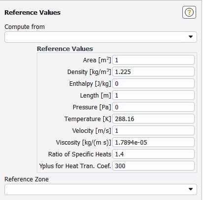
Figure 6. Reference values in ANSYS Fluent
At CFDLand, we offer comprehensive Heat Exchanger CFD Simulation tutorials that teach you how to extract desired variables out of the CFD simulation regarding overall heat transfer coefficient, nusselt number, etc.
Conclusion: Mastering Overall Heat Transfer Coefficient
The overall heat transfer coefficient is essential for successful thermal engineering design. Moreover, understanding the heat transfer coefficient formula Q = U × A × ΔT and thermal resistance calculations helps you design better heat exchangers and thermal systems. Whether working with flat walls, cylindrical tubes, or complex geometries, the overall heat transfer coefficient varies significantly based on fluid properties, flow conditions, and surface characteristics. From building insulation with U values of 1-5 W/m²·K to steam condensation exceeding 10,000 W/m²·K, knowing typical heat transfer coefficient ranges validates your calculations.
ANSYS Fluent CFD simulation revolutionizes heat transfer coefficient analysis for complex applications. Furthermore, CFD provides accurate overall heat transfer coefficient predictions that manual calculations cannot achieve, especially for real-world geometries with entrance effects and turbulence. At CFDLand, our Heat Exchanger CFD Simulation tutorials teach you to master ANSYS Fluent for calculating heat transfer coefficient values, modeling complex heat exchangers, and optimizing thermal performance. Ready to excel in thermal engineering? Explore our comprehensive Heat Transfer CFD Simulation tutorials and master overall heat transfer coefficient analysis today!
Related Blogs
Expand your heat transfer knowledge with these essential guides:
- Convective Heat Transfer: Deep dive into convection heat transfer coefficient fundamentals and applications
- Energy Conservation Equation: Master the energy equation used in heat transfer calculations
- Conjugate Heat Transfer (CHT): Learn advanced CFD simulation combining fluid and solid heat transfer
- Natural Convection: Understand natural convection heat transfer in fluid systems