


The Multiple Reference Frame Model
The Moving Reference Frame (MRF) model is a steady-state approach commonly used in ANSYS Fluent to simulate rotating machinery like fans, pumps, turbines, and mixers. This method divides the domain into rotating and stationary zones, applying rotation only to the fluid in the rotating region. As part of the Multiple Reference Frame model, it offers a reliable and computationally efficient solution for steady simulations. The MRF ansys fluent method is particularly effective under axial flow conditions and widely adopted in multiple reference frame CFD problems. However, it may under-predict fan performance at low to medium flow rates due to limitations in capturing radial and transitional regimes. These inaccuracies are most evident in fan performance curves where pressure rise is underestimated. Despite this, the ANSYS MRF method remains a powerful choice for engineers seeking balance between accuracy and speed, especially when modeling steady-state rotating systems in CFD.
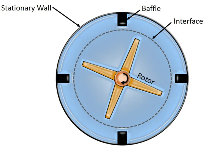
Figure 1- Top View of a Mixing System Featuring a Rotor, Baffle, and Interface in a Multiple Reference Frame (MRF) Simulation
Single Reference Frames (SRF)
In Single Reference Frame (SRF) modeling, the simulation is performed from the perspective of a rotating observer, meaning the rotating components are treated as stationary, and the fluid appears to move relative to them. This method is particularly useful when the entire flow domain rotates as a rigid body, such as in centrifugal pumps or rotating containers. The SRF approach simplifies the governing equations by incorporating centrifugal and Coriolis forces into the momentum equation in rotating frame of reference, allowing for steady-state analysis of rotational effects. While it is less flexible than the Multiple Reference Frame (MRF) method for complex geometries with both rotating and stationary parts, it is computationally efficient and accurate in cases where a single rotating frame suffices. The SRF method is commonly applied in CFD software like ANSYS Fluent, and is a useful alternative to MRF ANSYS Fluent in simplified rotating systems.
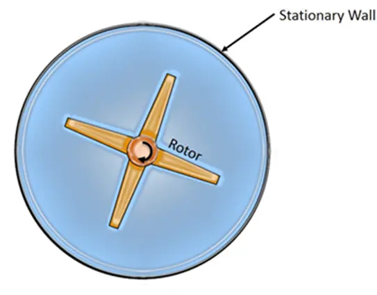
Figure 2- Top View of a Mixing System Featuring a Rotor and Interface in a Single Reference Frames (SRF) Simulation
Multiple Reference Frames (MRF) vs. Single Reference Frames (SRF)
The comparison table (Table1) between MRF (Multiple Reference Frame) and SRF (Single Reference Frame) highlights the key differences in how rotating machinery is modeled in ANSYS Fluent. While SRF assumes the entire domain rotates together, simplifying the setup and eliminating the need for interfaces, MRF allows for separate stationary and rotating zones, making it suitable for complex systems like pumps and mixers. MRF requires interface definition for proper data transfer between zones but offers greater flexibility and accuracy in simulating real-world rotating equipment.
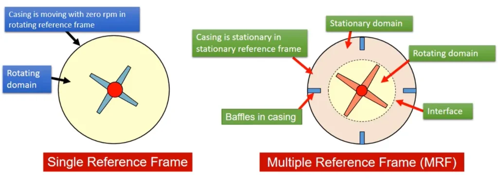
Figure 3- Comparison of Single Reference Frame and Multiple Reference Frame (MRF) Approaches in ANSYS Fluent for Mixing Systems
Table 1- Comparison between Multiple Reference Frames (MRF) and Single Reference Frames (SRF)
| Feature | MRF (Multiple Reference Frame) | SRF (Single Reference Frame) |
| Definition | The domain is divided into rotating and stationary zones. Each zone uses its own reference frame. | Entire simulation domain is treated from the perspective of a single rotating reference frame. |
| Application | Suitable for systems with both rotating and stationary parts (e.g., mixers, turbomachines). | Best for systems where the entire domain rotates (e.g., rotating containers, centrifugal pumps). |
| Fluid Motion | Rotational speed is applied only to the fluid in the rotating zone. | Rotational motion is applied to the entire fluid domain. |
| Flexibility | Highly flexible for complex geometries. | Limited to simpler configurations. |
| Computational Cost | Slightly higher due to multiple zones, but still steady-state and efficient. | Lower cost; simple to implement and fast to solve. |
| Accuracy | More accurate in capturing interactions between rotating and stationary parts. | Less accurate for systems with both rotating and non-rotating components. |
| Common Use in CFD | Widely used in ANSYS MRF simulations and multiple reference frame Fluent setups. | Applied in CFD when a single rotating frame suffices. |
ANSYS MRF vs. Sliding Mesh: Which Rotating Frame Model Should You Use?
In rotating machinery simulations such as fans, pumps, turbines, or mixers, engineers often face a critical choice: Sliding Mesh or the Multiple Reference Frame (MRF) model. This decision greatly impacts simulation accuracy, speed, and complexity—especially in ANSYS Fluent.
What is Sliding Mesh in CFD?
The sliding mesh method is a transient (time-dependent) approach where the mesh actually moves.
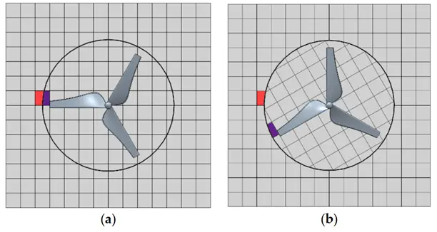
Figure 4- Mesh in a transient simulation using the sliding mesh approach: (a) the initial mesh at t=0s; (b) the rotated mesh at t > 0 s
This dynamic mesh technique is more accurate for problems involving strong rotor-stator interactions, blade passing events, or unsteady wakes. However, sliding mesh in Fluent requires very small time steps, generates a large number of time steps, and needs more computational power. Also, it uses non-conformal mesh interfaces, and interface zones can potentially penetrate each other, making the setup more complex.
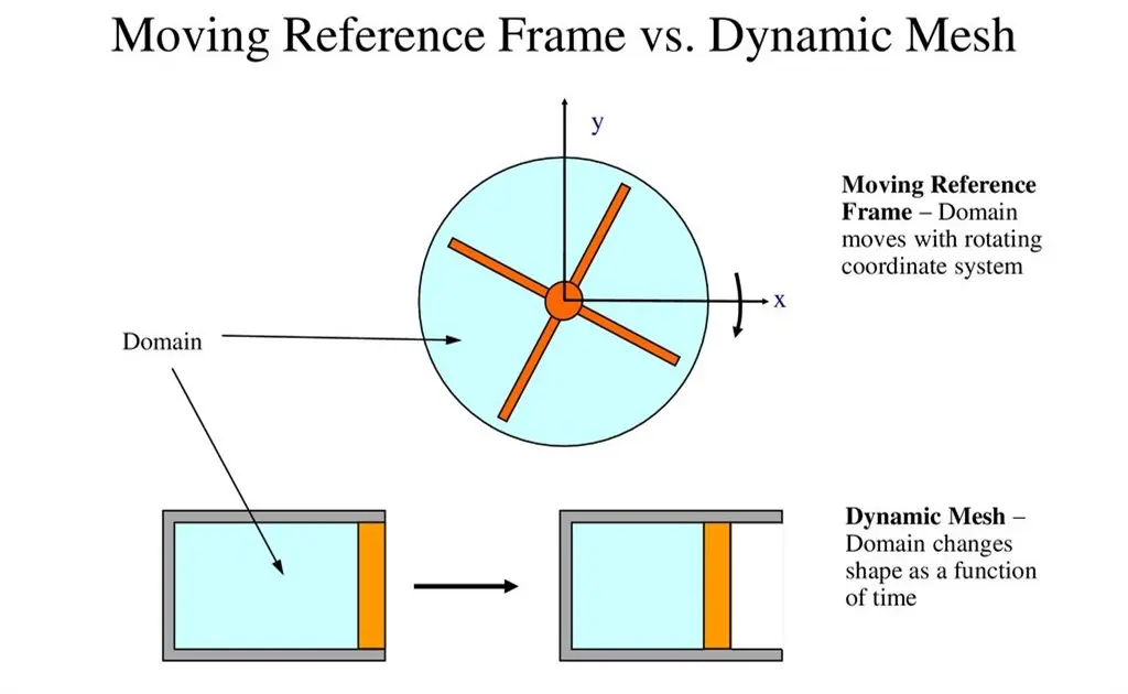
Figure 5- Comparison of MRF (Multiple Reference Frame) and Dynamic Mesh in CFD
Table 2- Comparison of MRF and Sliding Mesh in CFD
| Feature | MRF (Multiple Reference Frame) | Sliding Mesh Method |
| Simulation Type | Steady-state approach using a fixed mesh and rotating frame of reference | Transient (unsteady) simulation where the entire domain rotates with the rotating components |
| Mesh Motion | Mesh does not move, rotation is simulated mathematically via Moving Reference Frame (MRF) | The entire mesh zone physically rotates, increasing complexity |
| Time Step Size | Allows larger time steps and faster convergence | Due to convergence issues, it requires much smaller time steps |
| Mesh Interface | Typically uses conformal mesh between rotating and stationary zones | Interfaces are nonconformal, meaning mesh boundaries do not align, making setup more complex |
| Initial Conditions | Can be initialized with a steady-state assumption | Cannot start with a steady assumption; must be solved as a transient case |
| Computational Cost | Lower computational demand due to simpler mesh and steady solution | Requires significantly more computational power because of time stepping and mesh motion |
| Application Recommendation | Ideal for pumps, fans, or compressors in steady conditions | Recommended when fluid velocity is high, or for time-dependent interactions |
Multiple Reference Frames Formula: Understanding the Governing Equations
The Fig.5 visually illustrates the concept of Moving Reference Frames in CFD. On the left, the observer in the rotating frame sees the system as stationary and applies fictitious forces like Coriolis and centrifugal accelerations to explain the fluid motion. On the right, the observer in the stationary frame sees the object physically rotating, and the motion is described directly through the time-dependent rotation. This distinction is essential in CFD simulations, where selecting the appropriate reference frame (moving or stationary) impacts how the governing equations are formulated and solved. The MRF model leverages the rotating frame approach to simplify rotating flow problems in a steady-state framework.
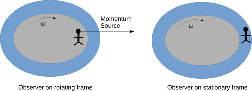
Figure 6- Comparison of Observers in Rotating and Stationary Reference Frames
When simulating rotating machinery using the Moving Reference Frame (MRF) approach in ANSYS Fluent, the Navier–Stokes equations are modified to account for the rotating coordinate system. This transformation allows for a steady-state approximation of rotating parts, such as impellers, fans, or turbines, without requiring complex transient mesh motion. When dealing with moving reference frames in CFD simulations—especially in ANSYS Fluent—the absolute velocity of a fluid particle in a rotating and translating frame is given by:

To evaluate flow properties like shear and strain in a rotating and translating system, the gradient of the absolute velocity vector is given by:

Therefore, governing equation: the momentum equation in rotating frame of reference and Continuity Equation can be modified as follows:
Conservation of Mass (Continuity Equation):

Conservation of Momentum in MRF:

Where 𝜌 is the fluid density, is the relative velocity in the rotating frame, is angular velocity of the rotating frame, is position vector, is stress tensor in the rotating frame, and is external body forces (e.g., gravity).
Note that scalar quantities such as density, static pressure, static temperature, species mass fractions, etc., are simply obtained locally from adjacent cells.
Also note the presence of additional acceleration terms, which have been placed on the right hand side. The first acceleration is called the Coriolis acceleration ( 2w*Vr), and has the property of acting perpendicular to the direction of motion of the fluid and to the axis of rotation. The second term is called the Centripetal acceleration (w*(w*r)) ), which acts in the radial direction. Both of these accelerations act as momentum source terms in the momentum equations, and can lead to difficulties if the rotational speed is very large.
MRF in ANSYS Fluent: Setup and Execution
ANSYS Fluent CFD simulation software is a very suitable option for simulating rotating components, either by sliding mesh, MRF, or SRF methods. The user can perform MRF and SRF simulations with the updated and advanced algorithms of this software and adjust the details of each method. In the simulation of rotating components, multiphase flow is often needed, or the flow is turbulent and needs to be simulated using various turbulent flow methods, or the deformation of rotating components needs to be considered (FSI simulations). ANSYS Fluent is a very powerful tool for all these challenges.
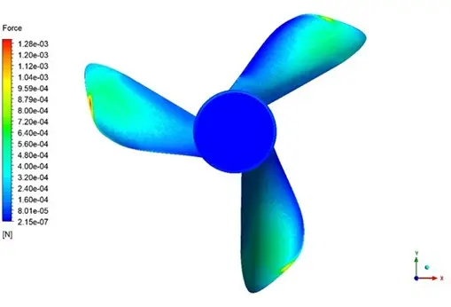
Figure 7- Force distribution wastewater sewage mixer, simulated by ANSYS Fluent. Adopted from “Wastewater Sewage Mixer with MRF CFD Simulation
Performing a simulation using MRF ANSYS Fluent involves several steps:
Geometry and Meshing
- Divide the geometry into stationary and rotating regions.
- Create a high-quality mesh, especially near the interface.
- Ensure that interface zones possibly penetrate each other are resolved by ensuring clear, clean interfaces.
Defining Zones
- Assign the rotating zone with the correct angular velocity.
- Use the multiple reference frame Fluent setup to define the motion.
Boundary Conditions
- Inlet and outlet conditions must be defined carefully to avoid unphysical reflections.
- At the interface, use the non-conformal interface or a frozen rotor model for better results.
Solution Methods
- Use the pressure-based solver.
- Enable rotating reference frame options for the rotating zone.
- Choose appropriate turbulence models (k-epsilon, SST k-omega, etc.).
Applications of the Moving Reference Frame (MRF) Method in CFD
The Moving Reference Frame (MRF) method is widely applied in Computational Fluid Dynamics (CFD) for modeling rotating equipment in a steady-state manner. This approach simplifies complex rotational motion by introducing rotational effects (like Coriolis and centrifugal forces) into the governing equations. ANSYS Fluent MRF is especially useful when the geometry is stationary in the rotating frame, and the flow can be assumed steady. Here are some major Multiple Reference Frames Examples and devices where is effectively used.
Turbomachinery Simulation with ANSYS MRF CFD
The Multiple Reference Frame (MRF) model in ANSYS Fluent is extensively used to simulate rotating components in turbomachinery, such as pumps, compressors, and turbines. These rotating blades interact with fluid flow at high speeds, and MRF ANSYS Fluent offers an efficient way to model steady-state flow fields around them. Using the moving reference frame (MRF) technique helps engineers optimize turbomachinery performance with reduced computational effort compared to transient methods.

Figure 8- Turbomachinery Simulation: Centrifugal Fan CFD Simulation in CFDLAND: Multiple Reference Frames Examples
Aerospace Applications of Multiple Reference Frame CFD
In aerospace engineering, rotating components like helicopter rotors and jet engine turbines require precise flow modeling. The moving reference frame Fluent, simulates steady-state flow around these parts efficiently. Many engineers follow ANSYS Fluent MRF tutorials to learn how to apply MRF for jet engine compressors and turbines. This approach avoids the complexity of full transient simulations while capturing essential aerodynamics effect.
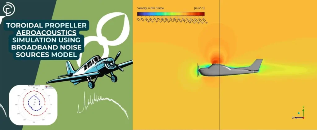
Figure 9- Toroidal Propeller Aeroacoustics Simulation Using Broadband Noise Sources Mode in CFDLAND: Multiple Reference Frame Tutorial
Marine Engineering and Moving Reference Frame CFD
Marine propulsion relies heavily on rotating propellers, which often experience cavitation and complex fluid interactions. The multiple reference frame CFD model in ANSYS Fluent enables simulation of these rotating parts under steady conditions. It handles the interface zones possibly penetrating each other between rotating and stationary domains by defining suitable interface boundaries. MRF ANSYS Fluent simulations are widely used for ship propellers and torpedoes to optimize performance and mitigate cavitation risks.
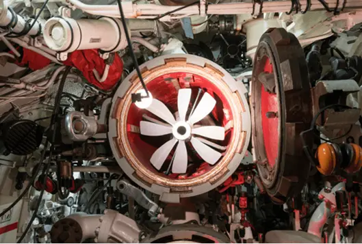
Figure 10- A torpedo can be seen from behind. Torpedoes, like ships, move using rotating components and blades. Therefore, the simulation of torpedo movement is a suitable application for the MRF method: Multiple Reference Frames Examples
Mixers and Rotating Equipment in Industrial Applications
Industries such as food processing and pharmaceuticals use mixers with rotating impellers. Applying moving reference frame Fluent methods allows steady-state simulation of multiphase mixing processes.

Figure 11- Mixers are a good choice for MRF and SRF simulations due to their rotating components: Multiple Reference Frames Examples
Biomedical Device Simulation with ANSYS Fluent MRF
In biomedical engineering, devices like centrifugal blood pumps and left ventricular assist devices benefit from MRF CFD simulation. Using the Multiple Reference Frame model in ANSYS Fluent helps predict blood flow patterns and shear stresses inside rotating components, improving device safety and function. Learning what is multiple reference frame in CFD helps engineers design better biomedical pumps by simulating realistic flow behavior.

Figure 12- Biomedical Device Simulation with ANSYS Fluent MRF in CFDLAND: Multiple Reference Frame Tutorial
Renewable Energy and MRF Applications in CFD
Renewable energy devices such as airborne wind turbines rely on efficient blade rotation. The moving reference frame model in ANSYS Fluent supports aerodynamic analysis of rotating blades, helping optimize energy capture. Many use multiple reference frames examples to understand how to apply MRF for wind turbine blade simulations in CFD.

Figure 13- Airborne Wind Turbine Using MRF CFD Simulation in CFDLAND, Multiple Reference Frame Tutorial
CFDLAND’s Expertise in MRF and SRF Simulations with ANSYS Fluent
At CFDLAND, we specialize in MRF (Multiple Reference Frame) and SRF (Single Rotating Frame) simulations using ANSYS Fluent. Our team has successfully completed numerous CFD projects involving rotating machinery, propellers, turbines, and mixers—all modeled with MRF ANSYS Fluent techniques. These high-quality simulations are optimized for performance, cavitation analysis, and steady-state flow prediction in rotating systems.
You can explore some of our MRF CFD simulation projects showcased at the top of this page. For a full list of our ready-made tutorials and case studies, visit the CFDSHOP, you might find the perfect solution for your simulation needs.
Trust CFDLAND’s professional CFD services and place your order through our ORDERPROJECT page. Whether you’re looking for a custom ANSYS Fluent MRF tutorial, or complete project delivery, we’re confident you’ll be impressed by the precision, quality, and engineering expertise we bring to every simulation.