


Porous media are materials that contain a network of interconnected pores or voids, allowing fluids to pass through them (Fig.1). Examples include soil, foam, filters, and biological tissues. From a fluid dynamics perspective, understanding fluid flow in porous media is essential for analyzing systems involving filtration, heat transfer, and chemical processing. Whether you’re new to the topic or looking to deepen your understanding, our website, CFDLAND, offers helpful porous media fluent tutorial and examples to guide you through the practical aspects of working with porous media in ANSYS Fluent and other CFD approaches. The porous media meaning in CFD context refers to regions in your model that introduce resistance to fluid flow—often needing special treatment in simulations like porous media fluent models.
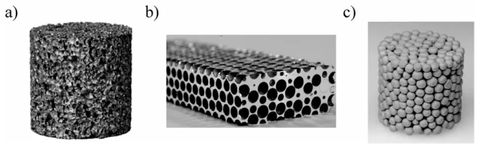
Figure 1- Different types of porous materials: a) closed-cell metal foam; b) hollow alumina spheres embedded in a magnesium matrix c) hollow sphere foam Fe0.88 Cr0.12 [1]
Porous Media Meaning
In materials science, a porous medium or a porous material is a material containing pores (voids). A fluid-saturated porous media consists of a matrix and a porous space, with the latter usually interconnected and filled by a fluid (effective porosity). The matrix is composed of solid material as well as some occluded porosity which is not an effective porosity and it may be saturated with fluid. In another approach, a porous medium is a combination of two continua, i.e. the skeleton continuum and the fluid continuum (Figure 2.1). The skeleton is composed of the matrix and connected porous space without any fluid, whereas the fluid continuum contains saturated porous space with fluid without any matrix.
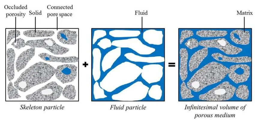
Figure 2- Porous medium as the superposition of skeleton particle and fluid particle in an infinitesimal volume[2]
Physical Characteristics of Porous Media
Let’s explore the physical characteristics that make fluid flow in a porous media a fundamental aspect of many disciplines, highlighting the importance of porous media flow and the detailed analysis of flow in a porous media.
Porosity
Porosity is the ratio of void volume to the total volume of a porous medium. The Fig.3 shows four cylindrical samples with different levels of porosity, ranging from 64% (most porous) to dense (no visible pores). The samples illustrate how increasing porosity results in more open structure, while the dense sample has a solid structure with minimal or no pores.
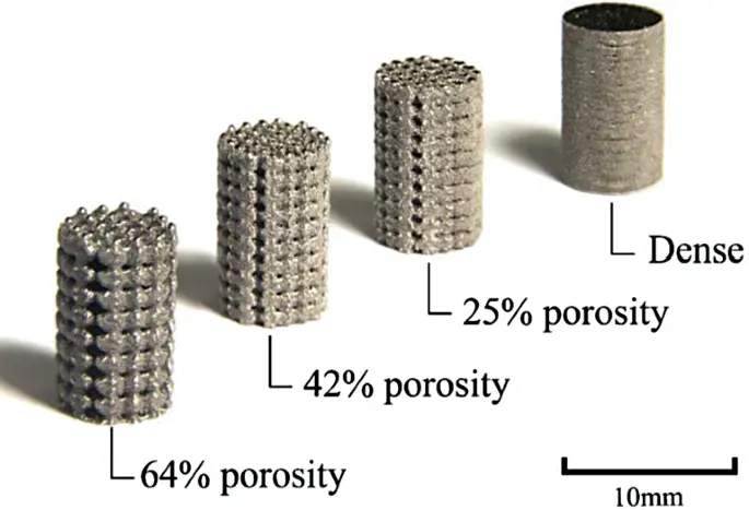
Figure 3- porous media filter: solid and porous Ti-Ta cylinders [3]
Permeability
The ability of a porous material to transmit fluids. It is a key property that determines how easily fluids can flow through the medium. Fig.4 shows how permeability decreases from gravel to clay, as water flows quickly through gravel but takes much longer to pass through sand, silt, and especially clay.

Figure 4- Permeability of different soil types: water flow rates through gravel, sand, silt, and clay
Tortuosity
Tortuosity is a measure of the complexity or lengthening of the flow path a fluid takes through a porous medium compared to the straight-line distance (Fig.5).

Figure 5- Comparison of Straight and Tortuous Flow Paths in Porous Media
Capillary Action
Capillary action is another remarkable physical characteristic seen in porous media, where fluid movement occurs against the force of gravity due to surface tension effects (Fig.6).

Figure 6- Effect of particle size and pore radius on capillary rise in porous media
Porous Media Equations
When analyzing fluid flow in a porous media, several key equations are used to model the movement of fluids through materials with internal voids. Moreover, the relationship between flow rate and pressure difference can be changeable for porous media flow. As shown in the Fig.7, the first part of the curve from the origin shows that the relationship is linear. When the flow rate is large, the non-linear relationship starts to show up.

Figure 7- Relationship between flow rate and pressure difference
The two primary equations often used in porous media modeling are Darcy’s Law and the Forchheimer equation, each addressing different flow conditions.
Darcy’s Law
For slow, steady flows where inertial effects are negligible, Darcy’s Law is commonly used to describe the fluid velocity (𝑣) in porous media. The equation is:

here, 𝑣 is fluid velocity, 𝐾 is permeability of the porous medium, 𝜇 is dynamic viscosity, and ∇𝑃 is pressure gradient. This simple yet fundamental relationship indicates that the flow rate is proportional to the pressure difference and the permeability of the material. It’s widely used in ANSYS Fluent porous media simulations when the flow is considered laminar and slow.
Forchheimer Equation
For higher velocities, where inertial effects become important, Darcy’s Law needs to be adjusted. The Forchheimer equation includes a correction term for inertial resistance:

here, 𝑆 is momentum sink/source term, 𝐶2 is inertial resistance coefficient, 𝜌 is fluid density and 𝑣 is fluid velocity. This extended equation is used when the flow through the porous media becomes turbulent or faster, and it’s essential for modeling more complex systems like those found in porous media ANSYS Fluent simulations.
Energy Equation
In many cases, heat transfer is also a critical part of porous media flow. The energy equation in porous media is similar to the standard heat transfer equation, but it includes the effects of the porous structure:

here, 𝑇 is temperature, 𝑘𝑒𝑓𝑓 is effective thermal conductivity and 𝑄 is volumetric heat source. This equation helps model fluid flow and heat transfer in porous medium, allowing engineers to predict temperature distributions within porous materials.
Governing equations
The governing equations for the steady flow are as follows:


where u = [u, v, w] T is the velocity vector, p is the pressure, ν is the kinematic viscosity and ρ is density. Sporous is the source term due to the presence of the porous media, and is only considered when using the porous media model. ANSYS Fluent uses the generalized formula to model porous media, as detailed in Fluent user manual (ANSYS Fluent User Guide, Release 15.0). The porous media model in ANSYS uses a superficial velocity inside the porous media instead of the actual velocity in the media. Thus, the model cannot predict the real velocity inside the media. However, it produces results for the pressure drop and velocity values. The modeling for the porous media uses the sink term Sporous, which is defined as follows ANSYS Inc (2013):

where D is the matrix of viscous resistance coefficients, which is a diagonal matrix containing the resistance coefficient corresponding to each direction. C is the matrix of inertial resistance coefficients, which has a diagonal form similar to the matrix D. The terms appearing in this equation called Darcy and Forchheimer drag terms.
ANSYS Fluent Porous Media Simulation
Porous media modeling involves representing fluid flow and sometimes heat transfer through a solid matrix containing interconnected voids. In CFD, this complex behavior can be effectively simulated using ANSYS Fluent, a powerful tool for Porous Media CFD applications. Fluids can move easily within a layer of the shale, but cannot move across layers (Fig.8).
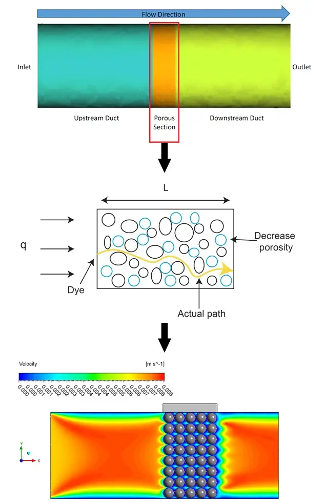
Figure 8- Example of fluid flow in a porous medium
If you’re wondering how to model porous media in Fluent, follow this typical workflow:
- Step1: Geometry Setup
When performing porous media modeling in ANSYS Fluent, the first and most crucial step is setting up the geometry correctly (Fig.9). This means clearly defining the domain and separating the porous region from any surrounding fluid zones.
- Think of the porous region as the area where the flow will experience resistance—like a filter, foam, packed bed, or rock formation.
- The rest of the domain might be open fluid flow regions (like inlets, outlets, or bypass channels).
- Clearly isolate the porous section as a separate body or volume so you can assign it a “Porous Zone” in Fluent later.
- Make sure interfaces between porous and non-porous zones are smooth to prevent meshing and convergence issues.
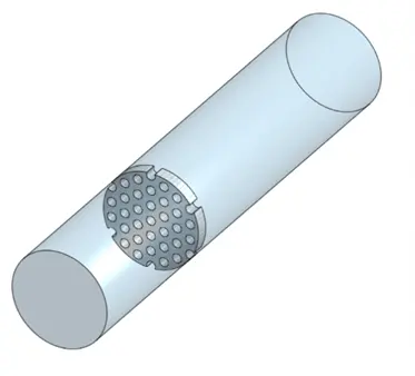
Figure 9- Schematic view of a porous media zone inside a pipe for CFD simulation in ANSYS Fluent
- Step2: Mesh Generation
Once your geometry is defined, the next step is to generate a mesh that captures the physical behavior of porous media flow. In porous media ANSYS Fluent simulations, the porous zone is treated as a continuum, so you don’t need to resolve individual pores. However, it’s still important to have adequate mesh resolution in the porous region to:
- Capture sharp pressure gradients
- Ensure stability and convergence
- Avoid excessive numerical diffusion
- Step3: Porous Zone Settings in ANSYS Fluent
Once you’ve defined your geometry and meshed the domain (with special care for accuracy in the porous region), you’ll need to assign the porous region in Fluent. Open the Cell Zone Conditions panel in Fluent (Fig.9), you need to designate the region that represents the porous media. Fig.10 shows the Direction Specification options for defining the main axes of resistance in a porous zone within ANSYS Fluent. When you select Cartesian, you are telling the software that you will define the resistance directions based on the standard X, Y, and Z axes, which is the most common and straightforward approach.
- Defining Directions:
- In 2D, you define one direction vectorfor resistance (for example, X or Y). The software automatically sets the other direction to be perpendicular (normal) to your chosen direction and the out-of-plane Z direction.
- In 3D, you must define two direction vectors. These should be perpendicular (normal) to each other. The software then calculates the third direction as being perpendicular to both (using the right-hand rule, similar to a cross product in vector math).
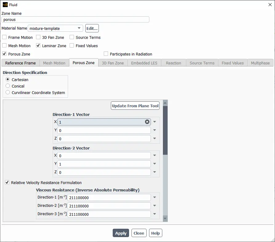
Figure 10- The schematic of porous media fluent panel: direction specification
Viscous and Inertial Resistance Coefficients
As mentioned, the momentum equation in a porous region is modified by adding a resistance term that accounts for the pressure drop due to the porous structure. Porous media in fluent formula is expressed as:


here, Si is the source term added to the momentum equation in the i-th direction (i = x, y, z), μ is dynamic viscosity of the fluid, α is Permeability of the porous medium, C2 is inertial resistance coefficient, ρ Fluid density, v is velocity magnitude and vi is velocity component in the i-th direction.
In fact, pressure drop in a porous medium arises from two main sources:
- Viscous resistance, which is due to frictional effects caused by the fluid’s viscosity and is most significant in laminar flow conditions.
- Inertial resistance, which stems from the loss of dynamic pressure or momentum and becomes more dominant in turbulent flow regimes.
In general, viscous effects dominate at low flow rates, while inertial effects become more prominent as velocity increases. In the highlighted red box of the Fig.11 you can see where viscous resistance coefficients are defined for the porous zone in ANSYS Fluent. These are specified under the label “Viscous Resistance (Inverse Absolute Permeability)” and correspond to three main directions—Direction-1, Direction-2, and Direction-3—which align with the primary axes of the porous region. By entering different values for each direction, you can simulate anisotropic porous media, where the resistance to flow varies with direction.
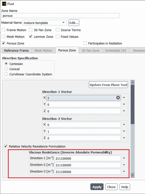
Figure 11- The schematic of fluent porous media: Viscous resistance setting
Fluid Porosity, Power Law Model, Thermal Model, Porous Material and Viscosity Model
As shown in the picture 12, porous media in fluent formula in ANSYS Fluent also allows the source term to be modeled as a power law of the velocity magnitude:

where 𝐶0 and 𝐶1 is are user-defined empirical coefficients.

Figure 12- The schematic of ANSYS Fluent porous media setting
Fluid Porosity: The fraction of the porous zone’s volume that is available for fluid flow (between 0 and 1). A value of 1 means the region is fully open, while a lower value means less space for flow. For example, the porosity is set to 0.3, which means that 30% of the porous zone’s volume is available for fluid movement, while the remaining 70% is occupied by the solid matrix of the porous material (Fig.13). You can also define the porosity using a user-defined function (UDF).
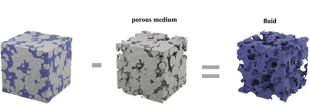
Figure 13- Imaginary schematic for better understanding the conception of fluid porosity
Defining the Porous Material: If you choose to model heat transfer in the porous medium, you must specify the material contained in the porous medium. To define the material contained in the porous medium, scroll down below the resistance inputs in the Fluid dialog box, and select the appropriate solid in the Solid Material Name drop-down list under Fluid Porosity.
Thermal Model: In ANSYS Fluent, the thermal model for porous media can be set to either thermal equilibrium or thermal non-equilibrium, depending on how you want to treat heat transfer between the fluid and solid phases inside the porous medium.
- Equilibrium:
Assumes the fluid and solid phases inside the porous region are at the same temperature. - Non-Equilibrium:
Allows the solid and fluid phases to have different temperatures (enables more advanced thermal modeling).
Relative Viscosity Model: This drop-down lets you select how the viscosity of the fluid is modified by the porous medium:
- constant:Fluid viscosity is not affected by the porous structure.
- brinkman, einstein, breugem:Different models for calculating effective viscosity in a porous medium, accounting for factors like porosity and solid phase interaction.
- user-defined:Lets you input a custom model.
- New Input Parameter:Define a new parameter for viscosity.
Conclusion
Mastering porous media modeling in ANSYS Fluent is vital for accurately simulating fluid flow and heat transfer in materials like filters, foams, and soils. The porous media ANSYS Fluent approach lets engineers define properties such as porosity, permeability, and resistance coefficients, enabling detailed analysis of both laminar and turbulent regimes. At CFDLAND, our team offers expert solutions for CFD porous media simulation projects using ANSYS Fluent porous media tools. We have many ready-made CFD porous media simulation projects in CFDLAND, which can be seen at the top of this page. Explore our ready-made projects or trust our experts to deliver high-quality, customized porous media Fluent simulations tailored to your engineering needs.