


Heat transfer through materials with many tiny holes, called “porous media,” is very important for many devices. Think of car radiators, filters, or even parts of rockets. These materials, like a Sintered Porous Channel CFD, help fluids mix better and create more surface area for heat to move. This makes them great for improving cooling or heating systems. Because of this, engineers have studied how fluids flow and how heat moves in these materials for many years. Our current study uses advanced computer tools, called Computational Fluid Dynamics (CFD), to look at a Sintered Porous Channel Heat Transfer CFD. We are specifically checking our computer model against a well-known research paper [1] to make sure our predictions are correct and reliable for real-world designs.
- Reference [1]: Jiang, Pei-Xue, and Xiao-Chen Lu. “Numerical simulation of fluid flow and convection heat transfer in sintered porous plate channels.” International Journal of Heat and Mass Transfer9-10 (2006): 1685-1695.
Figure 1- Schematic diagram of the Sintered Porous Channel physical model used in the CFD Simulation.
Simulation Process: Building a Digital Packed Bed for CFD
To perform the Sintered Porous Channel Fluent simulation, we first drew the physical system, which is a channel filled with many small, round particles, like the one shown in Figure 1. We used a computer program called Design Modeler to create this shape. After drawing, we divided the entire space into tiny pieces, called “tetrahedron elements,” using ANSYS Meshing. This creates a detailed map for the computer to solve the fluid flow and heat transfer. Since this is a Sintered Porous Channel VALIDATION CFD study, we made sure our setup matched the reference paper exactly. This included using the Forchheimer equation to describe how fluid loses pressure when it flows through the porous material. The Forchheimer equation helps us understand how the tiny holes and particles resist the fluid flow, and it has special numbers, like the coefficient ‘F’, that depend on how the porous material is built. The results are summarized in Table 2 of reference paper.


Post-processing: Comparing CFD Results with the Ergun Equation and Flow Visualization
The simulation results tell a clear story of cause and effect, starting with how well our model matches real-world data. Our first big finding is how accurately our Porous Heat transfer Validation CFD matched the important Forchheimer coefficient ‘F’ from the reference paper. The paper found ‘F’ to be 0.503, and our Sintered Porous Channel Heat Transfer Fluent simulation calculated it as 0.511. This is an incredibly small difference, only 1.8%. This tiny error means our computer model perfectly understands how fluids lose pressure when moving through porous materials. This close agreement is a major achievement of our Sintered Porous Channel VALIDATION CFD study, proving that our numerical setup and the physics models used in ANSYS Fluent are highly reliable for predicting fluid flow behavior in complex porous structures. This validation gives engineers strong confidence in using our method for designing efficient heat exchangers and filters.
Table 1: Forchheimer Coefficient Validation Results
| Reference Paper | CFD Simulation | Error (%) | |
| F | 0.503 | 0.511 | 1.8 |
Beyond just validating the pressure drop, our simulation also shows exactly how the fluid moves and how this affects heat transfer. Figure 2, the velocity distribution, shows a clear cause and effect. As the fluid enters the porous channel, it is forced to squeeze through the tiny gaps between the particles. This cause leads to the effect of the fluid speeding up significantly in these narrow spaces, shown by the bright red-orange areas where velocity reaches 0.08 meters per second. This fast flow helps to carry heat away. Also, we can see dark blue zones right next to each particle where the fluid slows down almost to zero. These “stagnation points” are important because they show where heat might build up or where fluid stays in contact with the solid surfaces for a longer time, which is key for heat transfer. The most important achievement of this Sintered Porous Channel Heat Transfer CFD analysis is its detailed visualization of these complex, localized flow patterns within the porous structure. This deep insight is crucial for engineers to truly optimize the design of porous heat exchangers, allowing them to arrange particles in ways that maximize both fluid mixing and surface contact, leading to much more effective cooling or heating systems.
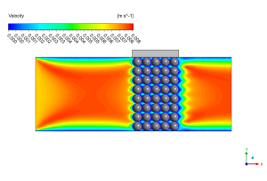
Figure 2: Velocity distribution along the porous zone from the Sintered Porous Channel Heat Transfer CFD analysis, showing fluid acceleration and stagnation points.


Reviews
There are no reviews yet.