


Understanding how fluids move through tiny holes and cracks is super important in today’s engineering world! Mixture transport in porous media represents one of the most challenging problems for engineers who need to predict how different liquids flow through rocks, soil, or industrial filters. When oil and water travel together through sand or special materials, their journey gets complicated because the permeability (how easily fluids can pass) changes from spot to spot. Modern CFD simulation tools like ANSYS Fluent can now solve these tricky problems, but only when enhanced with special code called User Defined Functions (UDF) that tell the computer exactly how the material properties change throughout the space. The fascinating world of multiphase flow in porous structures directly impacts countless real-world applications, from cleaning up dangerous groundwater contamination to maximizing production in valuable oil reservoirs. Moreover, the complex mathematics behind spatial variability of material properties becomes manageable through advanced computational methods that track each drop of fluid as it navigates the twisting paths inside porous materials. Transporting mixtures in porous media with location-dependent permeability is complex due to the porous structure’s spatial variability. This is our ultimate target in the present CFD study.
Simulation Process
A discretized rectangular channel establishes our computational domain, making out of structured grid. The mixture of oil and water plays the main role in which Mixture multiphase model is required. As the title suggests, the porous medium features from location-dependent permeability, known as Viscous Resistance in ANSYS Fluent. Thus, a specific user-defined function (UDF) is written, aiming to apply it. The permeability is governed by the following relation:

Post-processing
The simulation results show that there are different patterns in velocity and oil distribution within the channel and porous medium. The top picture shows an incredible view of how fast the mixture moves in different spots. We successfully captured the classic parabolic velocity profile that forms when liquids flow through a straight channel. See that bright red streak right down the middle? That’s where the mixture zooms along at its fastest speed (0.460 m/s) – almost half a meter every second! Meanwhile, the blue areas near the walls barely move at all, creating a beautiful speed gradient from edge to center. This happens because the walls grab onto the fluid molecules and slow them down, while the middle molecules can race freely forward. The perfect symmetry of the velocity pattern confirms our simulation is working correctly, and the smooth color transition from blue to red shows how the speed changes gradually rather than suddenly jumping from slow to fast.
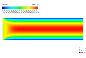
Figure 1: Velocity contour showing fluid flow speed distribution across the rectangular channel
Now check out the amazing oil-water separation in the bottom picture! We perfectly modeled the gravity-driven stratification process that happens when these two liquids flow together through our special porous material. The bright red zones at the top and bottom show where oil (with volume fraction of 0.95) has collected, while the deep blue middle section reveals the water-rich region (with almost zero oil). Notice how the oil layer at the top gets thicker as the mixture moves from left to right? This happens because our UDF creates changing permeability that affects how easily oil can flow in different parts of the channel. Also, look at those thin green-yellow lines between the red and blue areas – that’s the mixing zone where oil and water meet, staying remarkably thin and well-defined throughout the flow. This clean separation proves our simulation correctly handles the physics of how these two fluids interact while flowing through porous material with special properties that change from place to place!
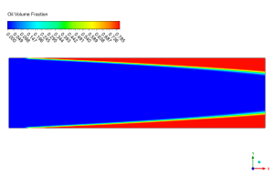
Figure 2: Oil volume fraction contour displaying phase separation between oil


Reviews
There are no reviews yet.