

Bioprinting with conical needles has changed how scientists can make living tissues in the lab! This amazing tissue engineering method uses special pointed needles to place living cells exactly where they need to go. First of all, conical needles allow for much better control when squeezing out delicate bioinks that contain living cells. Additionally, the unique shape of these needles helps the cell-laden materials flow more smoothly, which keeps more cells alive during the printing process. Moreover, improved cell viability means that the printed tissues work better and last longer after they’re made. Furthermore, the special tapered design creates just the right amount of pressure to push the thick bioink through without damaging the fragile cells inside. The bioprinting process using these special needles can create incredibly detailed 3D tissue models with multiple types of cells arranged in complex patterns. Most importantly, this technology brings us closer to making patient-specific implants from a person’s own cells, which could revolutionize how we treat injuries and diseases. The precise control offered by conical needle bioprinting helps scientists build complex biological structures layer by layer, just like using a very advanced 3D printer, but for living tissues! This growing field of personalized medicine continues to advance rapidly as engineers find ways to reduce cell damage during printing while creating ever more complex and functional living tissues. This vital application made it our outright target in this study, which is conducted based on the reference paper entitled “ MODELING MECHANICAL CELL DAMAGE IN THE BIOPRINTING PROCESS EMPLOYING A CONICAL NEEDLE”.
- Reference [1]: Li, Minggan, et al. “Modeling mechanical cell damage in the bioprinting process employing a conical needle.” Journal of Mechanics in Medicine and Biology05 (2015): 1550073.
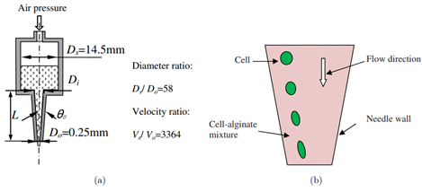
Figure 1: Typical bioprinting setup b) cell deformation inside needle [1]
Simulation Process
The tapered needle geometry is created based on the parameters given in Table 1 (reference paper). It is then discretized by a structured grid inside ANSYS Meshing (100000 cells). The fluid carrying mechanical cells is a cell-alginate mixture.
Post-processing
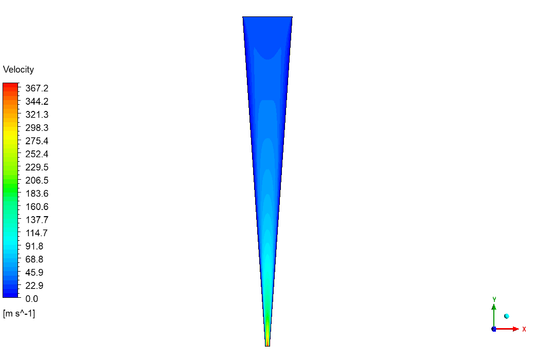
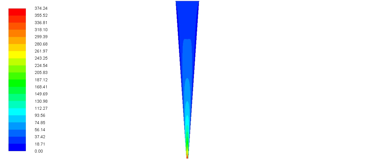
The velocity patterns inside the conical needle show us exactly why cells get damaged during bioprinting! As the bioink containing living cells squeezes through the needle, it speeds up dramatically from the wide end to the narrow tip. Our simulation successfully captured velocity increases from nearly 0 to a maximum of 367.2 meters per second at the narrowest point of the needle. This means the cell-carrying fluid speeds up about 16 times faster within just this small space! Also, notice how the flow pattern changes shape as the needle narrows! Furthermore, this rapid speed change forces cells to stretch and deform as they rush through the tip. Most importantly, cells near the center move faster than those near the walls, which creates stretching forces that can tear delicate cell membranes. This speed difference explains why many bioprinting systems struggle with poor cell viability after printing.

Figure 2: Velocity distribution through the conical bioprinting needle
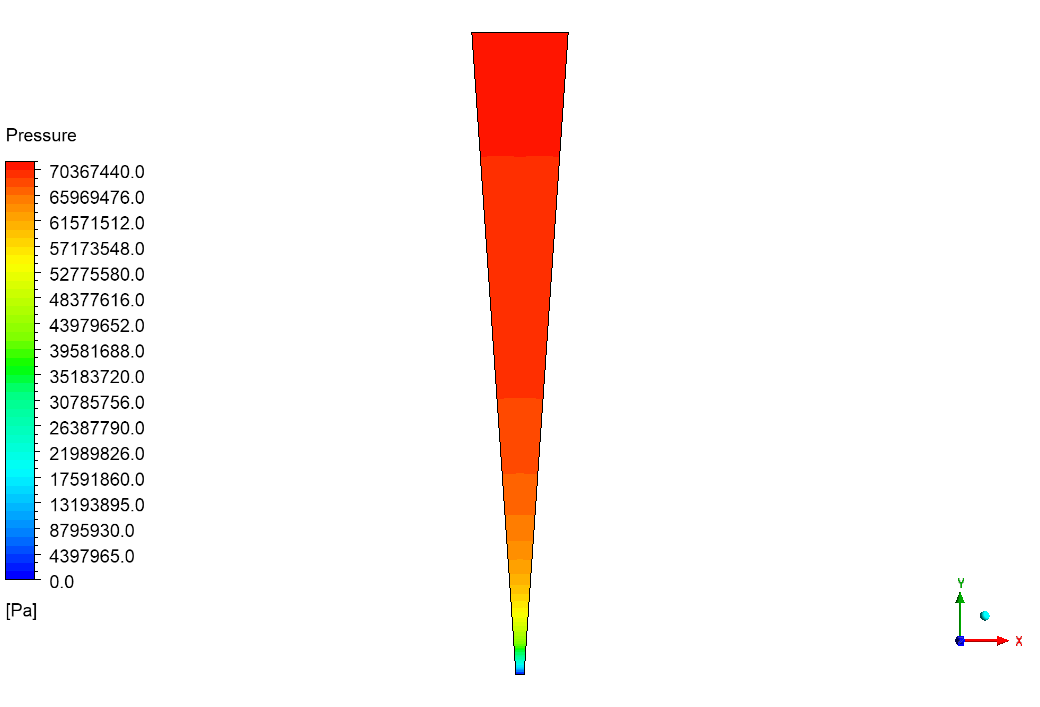
The wall shear stress graph shows us the biggest problem spot for cell damage during the printing process! The stress on cells skyrockets right at the narrowest part of the conical needle. Our analysis measured peak wall shear stress reaching an enormous 4,100,000 Pascal, which is thousands of times higher than what most cells can handle without damage. Additionally, this extreme stress happens in just a tiny section of the needle where it narrows the most. Most importantly, this explains why cells often die after bioprinting – they get crushed by these huge forces as they squeeze through the tip! The graph also shows how the stress drops quickly before and after this danger zone, creating a very sudden and harmful stress spike. This valuable information helps engineers design better bioprinting needles with gentler transitions that keep more cells alive during the printing process!
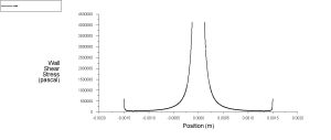
Figure 3: Wall shear stress distribution across the needle


Reviews
There are no reviews yet.