


When it comes to rocket engines, a big question rises. Ever wonder how rockets don’t melt their launch pads? This CFD Study focus on how to simulate a flame deflector design using ANSYS Fluent! Flame deflectors are super important parts that redirect hot engine exhaust away from critical equipment. Our step-by-step guide helps you set up a complete CFD simulation to see how these exhaust deflectors handle the extreme heat and pressure from rocket or jet engines. You’ll learn how to model the intense flame impingement that happens when super-hot gases hit the deflector surface at high speeds. This type of flame deflection system simulation helps engineers design better heat protection for test stands, launch pads, and engine testing facilities. Using computational fluid dynamics for flame deflector design saves countless hours and millions in testing costs! This tutorial explains complex rocket exhaust flow in super simple terms and shows amazing visualizations of how flame diversion works. Whether you’re designing a small engine test facility or a massive rocket launch complex, understanding proper deflector geometry is critical for safety and performance. In addition, we have used the guidance of reference paper:
- Referece [1]: Zhou, Zhitan, Liangjun Zhang, and Guigao Le. “Numerical study for the flame deflector design of four-engine liquid rockets.” Engineering Applications of Computational Fluid Mechanics1 (2020): 726-737.
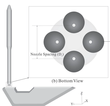
Figure 1: Design of the flame deflector for the four-engine rocket [1]
Simulation Process
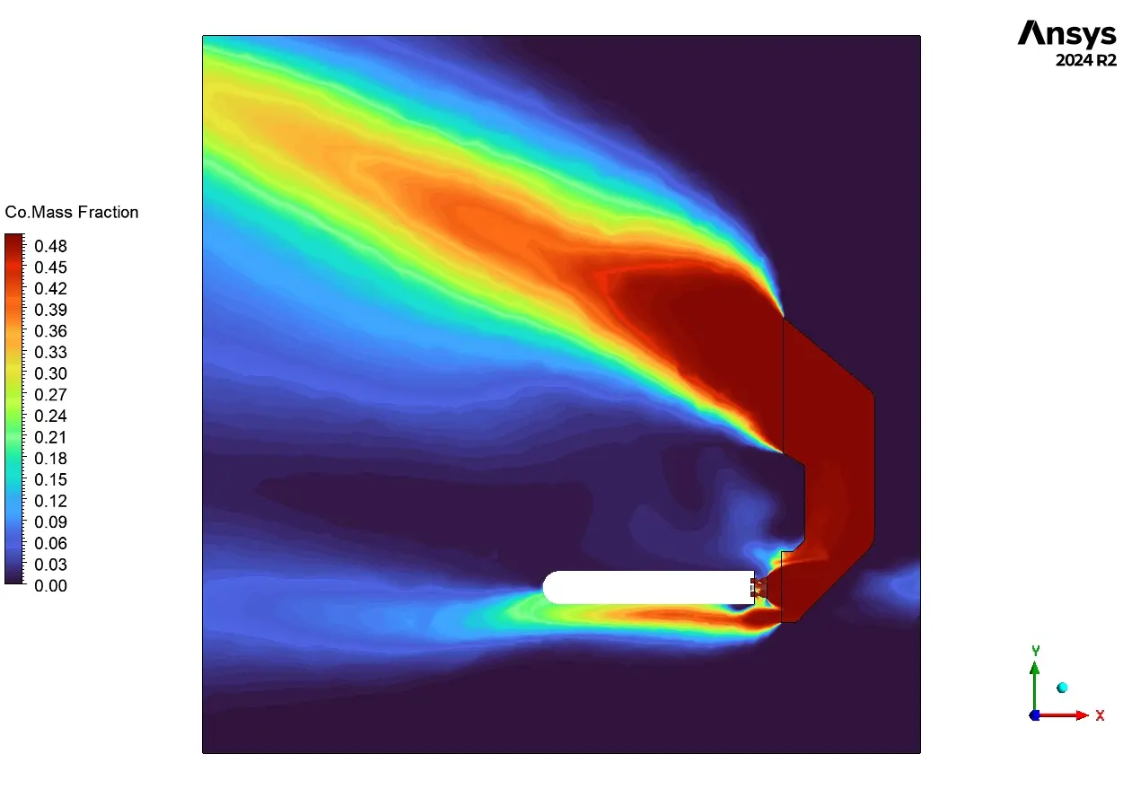
For our flame deflector simulation, we started by creating detailed 3D models of both the rocket motor and the deflector structure. The motor includes a converging-diverging nozzle that accelerates exhaust to supersonic speeds, while the deflector features curved surfaces designed to smoothly redirect the flow without excessive pressure buildup. We imported this geometry into ANSYS Fluent Meshing and created a high-quality. Since we’re dealing with extreme conditions, we set up a compressible flow condition. For combustion chemistry, we activated the species transport model to track multiple exhaust components including CO2, CO, water vapor, and hydroxyl radicals. This helps us understand both the flow dynamics and potential material erosion from chemical reactions.
Post-processing
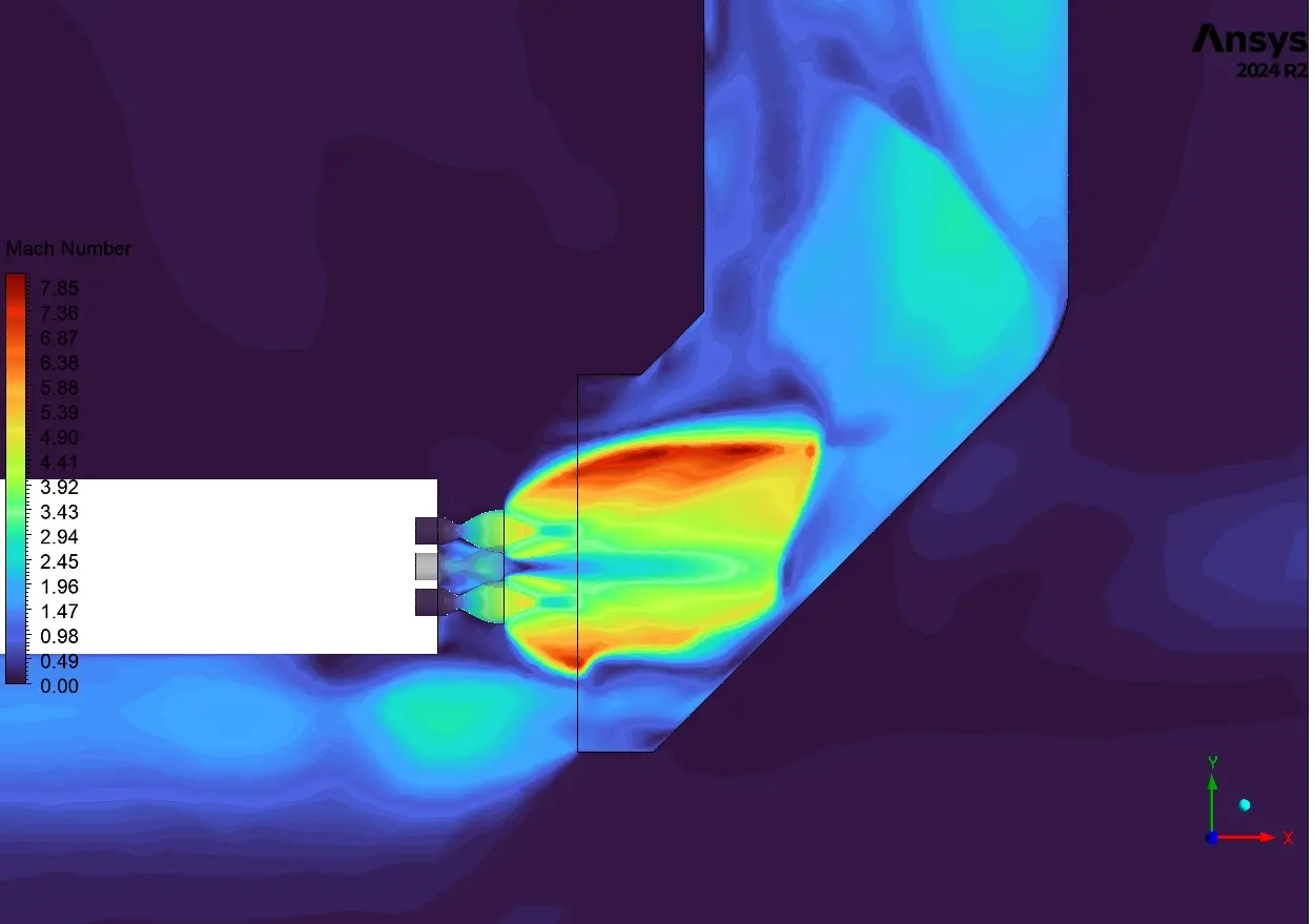
The Mach number contours shows supersonic flow patterns that explain exactly how our flame deflector handles the rocket exhaust. Notice the bright yellow-green region (Mach 5-7) where the flow accelerates as it expands around the deflector curves. This creates several key features that would be impossible to study without CFD simulation. First, we can clearly see the primary shock wave forming where the supersonic flow meets the deflector, causing an abrupt change from dark blue (subsonic) to bright green (supersonic). What’s particularly interesting is the secondary shock pattern developing on the upper side of the deflector, showing Mach numbers reaching an impressive 7.85 at the peak spots. From a design perspective, these areas of extreme velocity will experience lower static pressure but higher dynamic loading – critical knowledge for structural engineers. The flow separation zone visible at the bottom edge of the deflector (dark blue region) shows where the exhaust gases detach from the surface, creating recirculation that could trap hot gases and cause localized heating. This pattern suggests we might need additional cooling in that specific region to prevent material failure during extended engine firing.
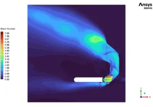
Figure 2: Mach number Distribution
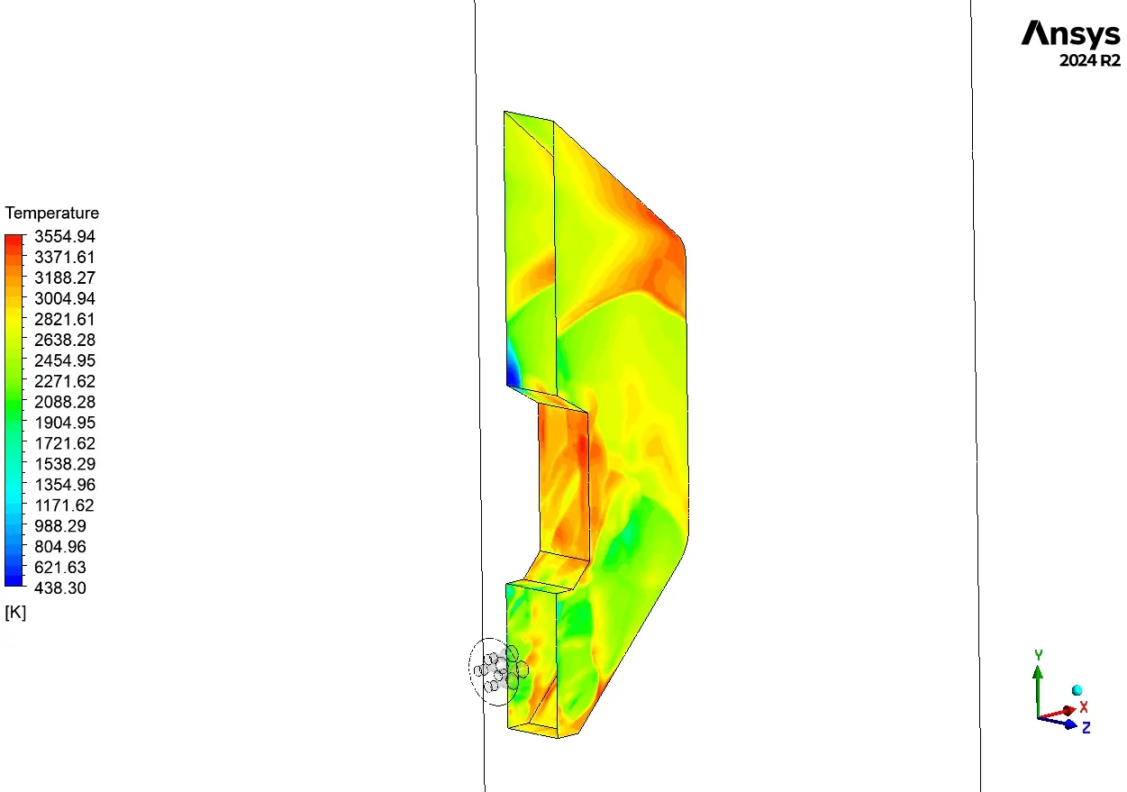
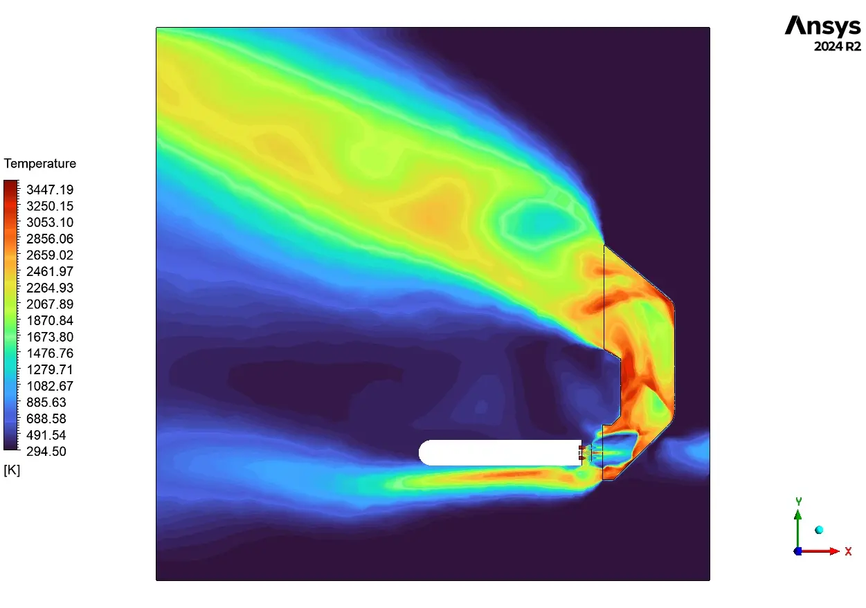
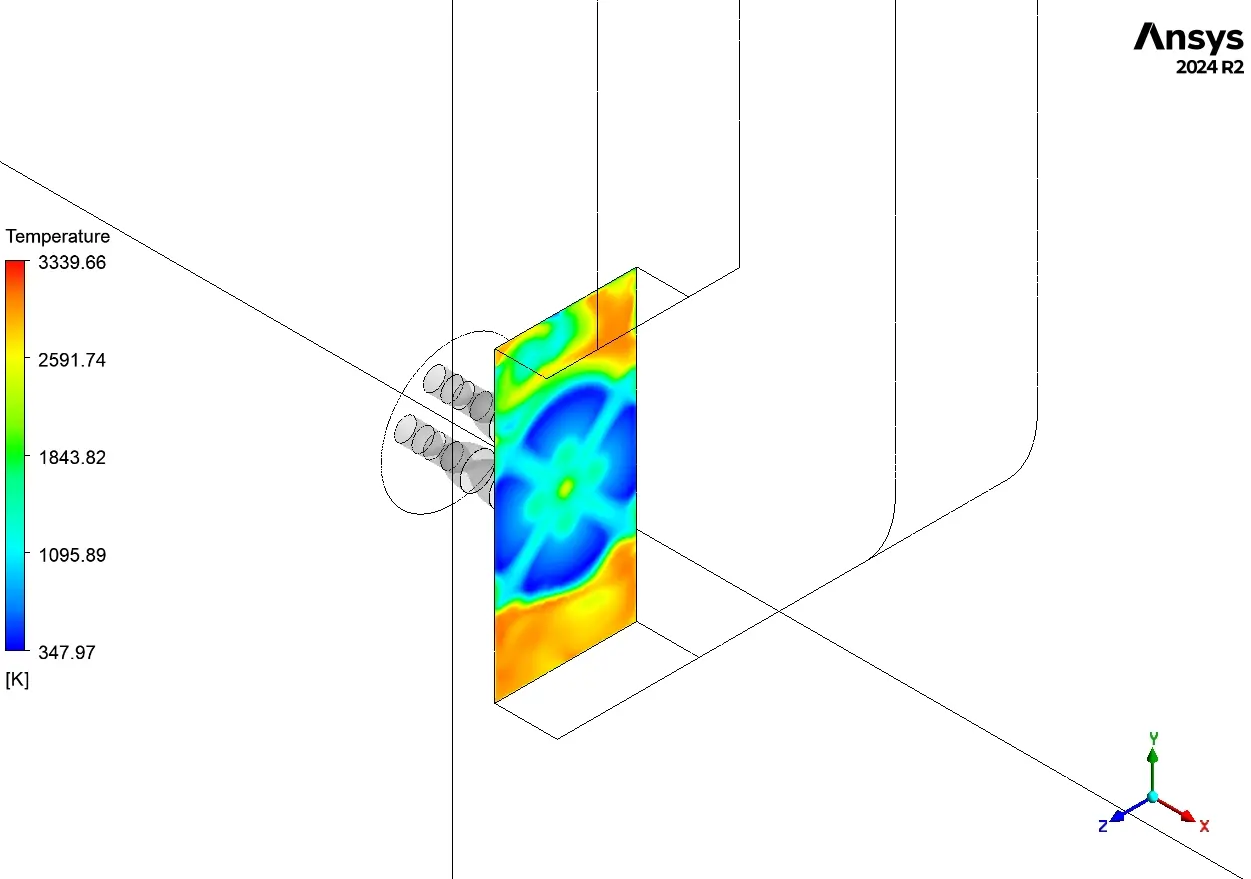
The temperature visualization depict the most critical aspect of flame deflector design – managing extreme heat. Looking at the streamlines in Figure 2, we can immediately see how temperatures exceed 4600K in the core flow – hot enough to melt virtually any metal! What’s remarkable is how the deflector design creates a protective boundary layer along its surface. Notice how the streamline colors transition from yellow-orange (3000-3500K) in the main flow to darker red (1400-2000K) near the walls – evidence that our design is working to minimize direct contact with peak temperatures. Figure 3’s cross-section view confirms this cooling effect but highlights potential problem areas where temperatures reach 3400K at impingement points. The three distinct flow channels visible in the deflector are clearly performing differently – the center channel shows higher temperatures (green-yellow regions around 1800K) compared to the outer channels, suggesting uneven heat distribution. Most concerning is the intense heating visible at the corner transitions where the flow turns sharply. These “hot spots” would likely require additional cooling solutions like water injection or special high-temperature coatings. The temperature gradient from the hot core flow (red, 3000K+) to the cooler surrounding air (blue, 300K) shows how effectively the deflector contains and directs the exhaust plume, preventing dangerous hot gas recirculation that could damage the engine or supporting structures above.
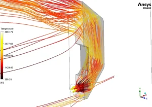
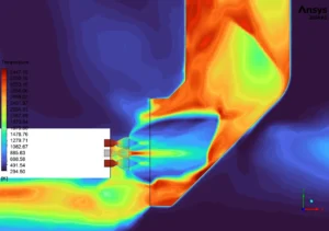
Figure 3: Temperature Analysis


Reviews
There are no reviews yet.