

This study introduces a CFD simulation designed to validate the analytical solution presented in Example 8-2 of Cengel’s Fluid Mechanics [1] textbook (Fourth Edition). The issue refers to the examination of oil flow within a pipeline of 28 centimeters in diameter, with a 330-meter stretch over cold lake waters. The oil possesses distinct characteristics: a density (ρ) of 894 kg/m³ and a dynamic viscosity (μ) of 2.33 kg/m·s, flowing at an average velocity of 0.5 m/s. The basic goal is to determine the pumping power necessary to counteract pressure losses and sustain flow, excluding entry effects. This case study, presented as the second session example in the ANSYS Fluent Course for Beginners, offers a valuable chance to compare numerical simulation findings with acknowledged analytical responses, thereby confirming both methodologies and deepening our comprehension of pipe flow dynamics. Note that, this is SESSION 2 of ANSYS Fluent Course For Beginners.
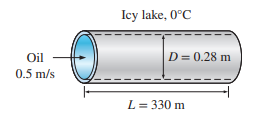
Figure 1: Flow through a Pipe CFD Simulation, Analytical Solution Validation [1]
- Reference [1]: Cengel, Yunus, and John Cimbala. Ebook: Fluid mechanics fundamentals and applications (si units). McGraw Hill, 2013.
Solution Process
The initial 2D design of 300-meter pipe is design using Design Modeler software regarding the symmetric nature of the problem, supporting by axisymmetric planar model. Then, it is meshed by ANSYS Meshing, resulting in 52800 quadrilateral grid (Structured mesh). One of the key elements of the problem belongs to consideration a fully-developed flow by adoption of Profile at the inlet. Based on the calculated Reynolds and literature, the flow regime remains laminar through the pipe.
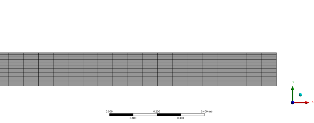
Figure 2: A cut-view of generated structured grid over Flow through a Pipe CFD
Post-processing
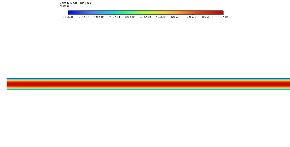
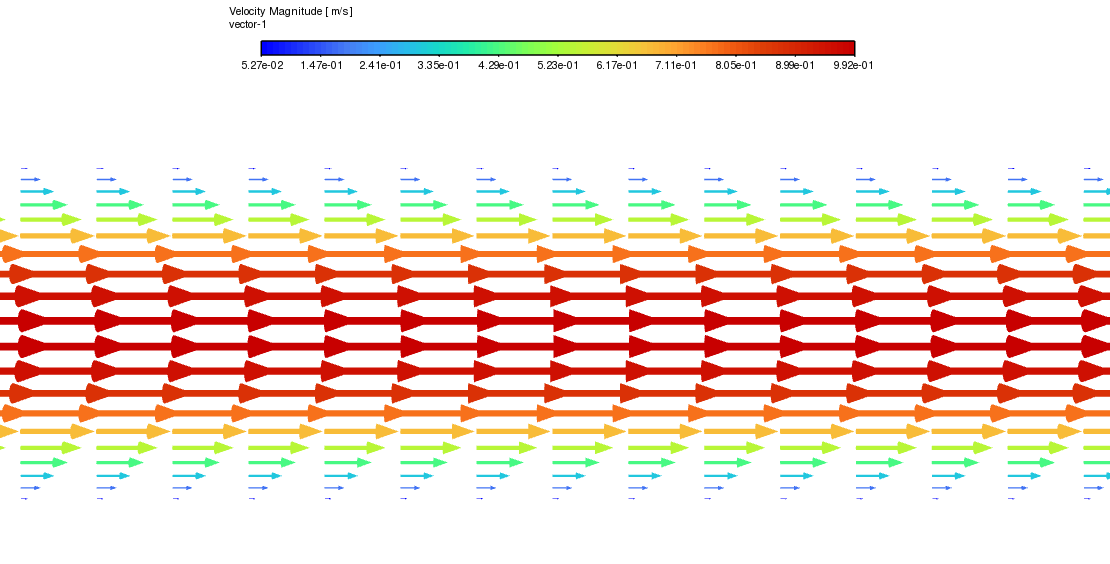
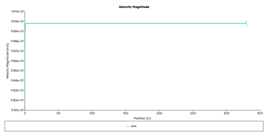
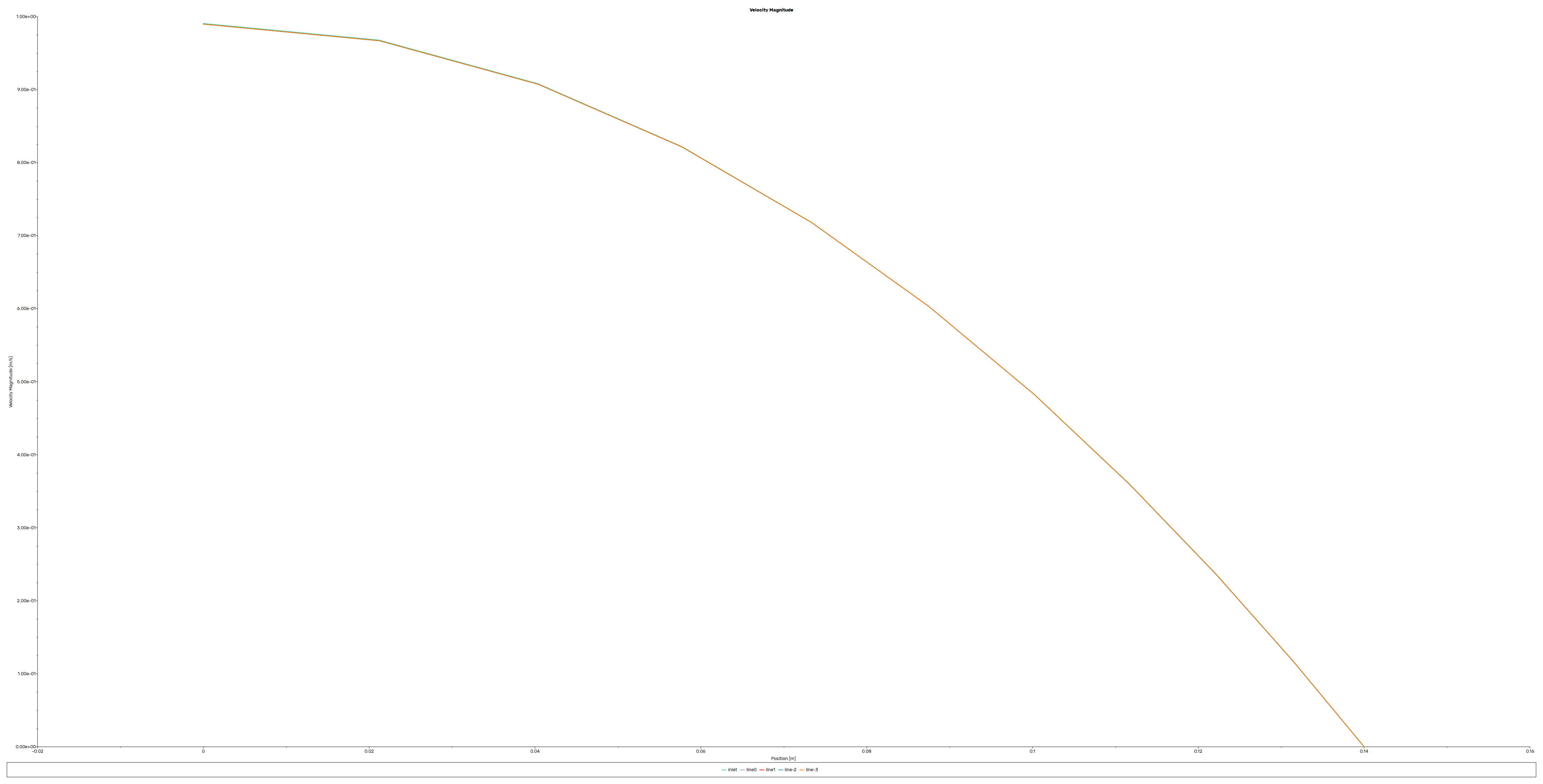
The combination of analytical and CFD findings clarify significant insights regarding flow characteristics and solution precision. The analytical solution confirms laminar flow conditions with a Reynolds number of 53.72, far lower than the critical threshold of 2300 [1]. The velocity contours and vector plots from the CFD simulation distinctly illustrate the parabolic profile typical of laminar pipe flow, featuring maximum velocity at the center and zero velocity at the walls due to non-slip shear condition. This qualitative agreement supports the laminar flow theory employed in both methodologies.
Analytical Solution:
Reynolds number: Re = ρVD/μ = (894)(0.5)(0.28)/(2.33) = 53.72
Friction factor: f = 64/Re = 64/53.72 = 1.191
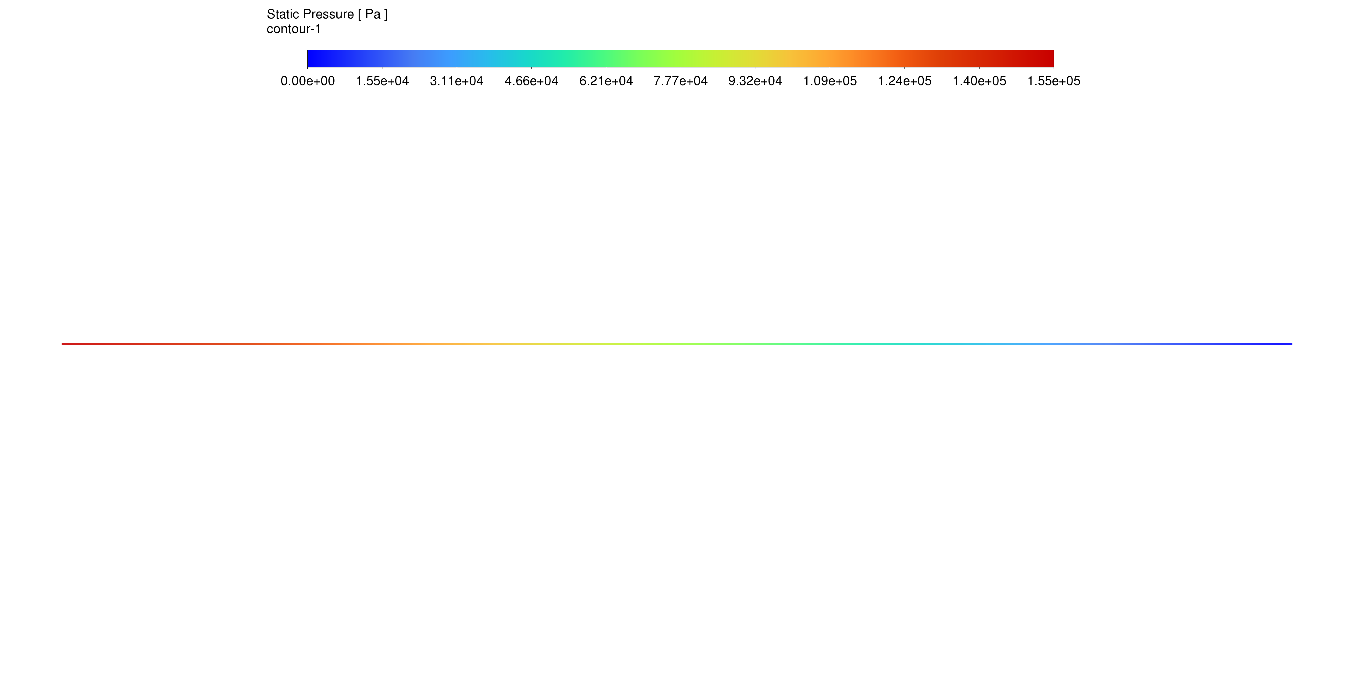
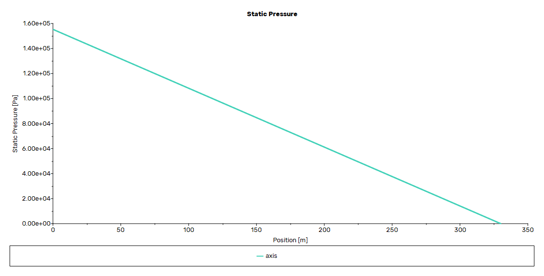
Pressure drop: ΔP = f(L/D)(ρV²/2) = 156.9 kPa
The quantitative comparison between CFD and analytical results demonstrates remarkable concordance in both pressure drop and friction factor calculations. The CFD simulation produced a pressure drop of 155.29 kPa, in contrast to the analytical value of 156.9 kPa, and a friction factor of 1.17, compared to the analytical value of 1.191. The close correlations, exhibiting errors of 1.02% in pressure drop and 1.76% in friction factor, illustrate the great precision of the CFD simulation in predicting pipe flow characteristics. The velocity profiles and pressure distributions derived from the CFD analysis robustly verify the accuracy of the analytical solution presented in the textbook.
CFD Results:
- Average wall shear stress: τw = 32.94 Pa
- Friction factor: f = 8τw/(ρV²) = (8)(32.94)/(894)(0.5²) = 1.17
- Pressure drop: ΔPCFD = 155.29 kPa
| Analytical Solution | CFD Simulation | Error (%) | |
| Pressure Drop | 156.9kPa | 155.29kPa | 1.02 |
| Friction Factor | 1.19 | 1.17 | 1.76 |

Figure 3: Velocity vectors of flow through a pipe CFD Simulation


Reviews
There are no reviews yet.