


In fluid dynamics, one of the most important phenomena is what happens when a fast-moving fluid touches a slow-moving fluid. The invisible boundary where they meet is called a shear layer or a mixing layer. Understanding this layer is critical for designing airplane wings and jet engine combustors. To study this invisible collision, engineers use a Mixing Layer CFD simulation.
This report is a complete Mixing Layer fluent simulation educational tutorial. We use ANSYS Fluent to visualize how a simple speed difference turns into chaotic turbulence. While phenomena like Droplet Formation in Microfluidic Device fluent simulations deal with perfectly smooth, slow multiphase flows, a mixing layer is the exact opposite. it is violent, fast, and highly turbulent. By mastering this CFD Analysis of Turbulent Mixing Layer, you will understand the root cause of aerodynamic mixing. For more foundational lessons on fluid behavior, please visit our Fluid Mechanics tutorials.
- Reference [1]: Goebel, Steven G., and J. Craig Dutton. “Experimental study of compressible turbulent mixing layers.” AIAA journal4 (1991): 538-546.
Figure 1: Experimental Schlieren photograph from the reference paper [1] (Goebel and Dutton), showing the large turbulent structures of a real-world mixing layer.
Simulation Process: K-Omega SST and Mesh Setup
To create this Turbulent Mixing Layer simulation, we built a 2D rectangular channel model. The setup has two parallel inlets: a high-velocity stream enters at the top, and a low-velocity stream enters at the bottom. We used a highly refined, structured mesh. We packed thousands of tiny calculation cells perfectly along the centerline where the two streams crash into each other. Because a Turbulent Mixing Layer is incredibly unstable, standard math cannot solve it. We activated the k-ω SST turbulence model in ANSYS Fluent. This specific model is an industry standard because it is highly accurate at predicting the exact moment when smooth flow breaks down and transitions into chaotic turbulence.
Post-processing: Analytical Story of Shear Instability
To truly understand this Mixing fluent study, we must look strictly at the cause-and-effect physics shown in the simulation data. We will explain exactly how a straight line of air turns into a swirling storm. The entire process starts at the inlet. Look at the Velocity Contour (Figure 3). The top stream is moving very fast (colored Red). The bottom stream is moving much slower (colored Blue). Because fluids have friction, the fast red stream rubs against the slow blue stream. In simple terms, the fast fluid “trips” over the slow fluid. This friction creates a “shear layer.”
A straight shear layer is physically unstable. Any tiny bump or vibration will cause the straight line between the red and blue streams to wobble. Look again at Figure 3. Moving from left to right, you can see the straight interface begin to wave. Suddenly, the fast air pushes down, and the slow air pushes up. This causes the fluid to roll up into distinct, swirling circles called vortices. This specific physical event is called the Kelvin-Helmholtz instability. This is the first critical step of mixing: the fluids are no longer separated by a flat line; they are now folded into a spiral. As these large, rolling vortices move further down the pipe, they stretch and violently tear apart into smaller and smaller pieces, creating full turbulence. This turbulence acts like a giant blender, mixing the fast and slow fluids together at a microscopic level.
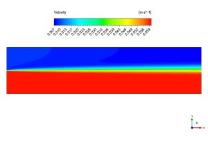
Figure 2: Velocity contour showing the Kelvin-Helmholtz instability. The initially straight interface rolls up into large-scale, swirling vortices between the fast (red) and slow (blue) streams.
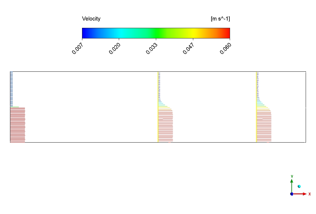
We can mathematically prove this blending by looking at the Velocity Profile (Figure 2). At the very beginning of the pipe, the velocity graph would look like a sharp cliff, jumping instantly from high to low. However, further downstream, the graph transforms into a smooth “S-shape”. This S-shape is the ultimate proof of Mixing Layer ANSYS Fluent success. It shows that the fast fluid has smoothly shared its momentum with the slow fluid, creating a perfect, gradual transition zone. This simulation perfectly demonstrates how a simple speed difference (the cause) naturally creates Kelvin-Helmholtz vortices, which then break down to create a perfectly blended turbulent flow (the final effect).
 624
624
Figure 3: The classic “S-shaped” velocity profile, proving that turbulent mixing has created a smooth transition between the high-speed and low-speed streams.
Key Takeaways & FAQ
- Q: What is a shear layer?
- A: A shear layer forms when two parallel streams of fluid travel at different speeds, creating friction and instability where they touch.
- Q: What is the Kelvin-Helmholtz instability?
- A: It is the physical phenomenon seen in Figure 3 where the friction between the fast (red) and slow (blue) fluids causes the straight boundary to wave and roll up into swirling circular vortices.
- Q: Why does the velocity profile become “S-shaped”?
- A: As the vortices break down into turbulence, the fast and slow fluids mix together. The sharp difference in speed is blended out, creating the smooth, S-shaped gradual transition shown in Figure 2.


Reviews
There are no reviews yet.