


Modern electronics, such as computer chips and processors, generate a lot of heat. If they get too hot, they fail. To solve this, engineers use Microchannels, which are tiny tubes that carry cooling liquid. However, a smooth tube is sometimes not enough. This is where the Grooved Microchannel comes in. By cutting small shapes (grooves) into the walls, we can force the liquid to mix better. In a smooth channel, the hot liquid sticks to the wall and the cold liquid stays in the center. The grooves break this pattern, pushing the cold liquid to the hot wall to remove heat faster.
In this Grooved Microchannel CFD simulation, we explore how to optimize this cooling method. We use ANSYS Fluent to simulate the flow of a nanofluid (liquid with tiny particles) inside a channel with trapezoidal grooves. This study is not just a demonstration; it is a validation based on scientific papers by Wu & Zhang (2021) and Wang et al. (2017). We compare our CFD analysis results with their experimental data to ensure accuracy. This ANSYS Fluent tutorial helps you understand how to model enhanced heat transfer for advanced electronics. For more cooling strategies, please visit our Microfluids & Nanofluids tutorials.
- Reference [1]: Wu, Huajie, and Shanwen Zhang. “Numerical Study on the fluid flow and heat transfer characteristics of Al2O3-water nanofluids in microchannels of different aspect ratio.” Micromachines8 (2021): 868.
- Reference [2]: Wang, Ruijin, et al. “Analysis and optimization of trapezoidal grooved microchannel heat sink using nanofluids in a micro solar cell.” Entropy1 (2017): 9.
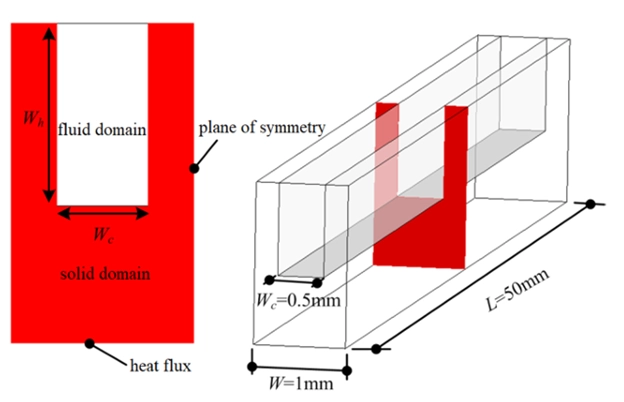
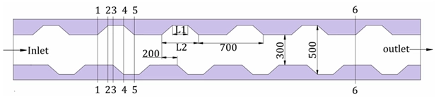
Figure 1: Schematic of the heat sink showing the trapezoidal grooved microchannel geometry.
Simulation Process: Single-phase nanofluid in Fluent
To begin this Grooved Microchannel CFD analysis, we needed to build a precise computer model. We first created a standard smooth microchannel based on Reference [1] to establish a baseline. After verifying that, we designed the complex grooved microchannel geometry using Reference [2]. The design features trapezoidal grooves arranged in a staggered pattern on the channel walls. These grooves are critical because they act as “turbulators,” disrupting the flow to enhance cooling.
The next step in this ANSYS Fluent simulation was meshing. A high-quality mesh is essential for capturing the complex flow inside the small grooves. We generated a fully structured grid containing exactly 2,168,100 cells. We chose a structured mesh because it provides better accuracy and convergence than an unstructured one, especially for thermal boundary layers. Finally, we set up the physics in ANSYS Fluent. We treated the nanofluid using a single-phase approach, assuming the fluid and particles are a perfectly mixed continuum. We applied specific heat flux conditions to mimic a hot electronic chip and set the solver to calculate the temperature changes.
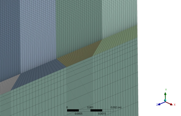
Figure 2: Fully structured mesh grid generated for the grooved microchannel CFD analysis.
Post-processing: Thermal Improvement and Validation
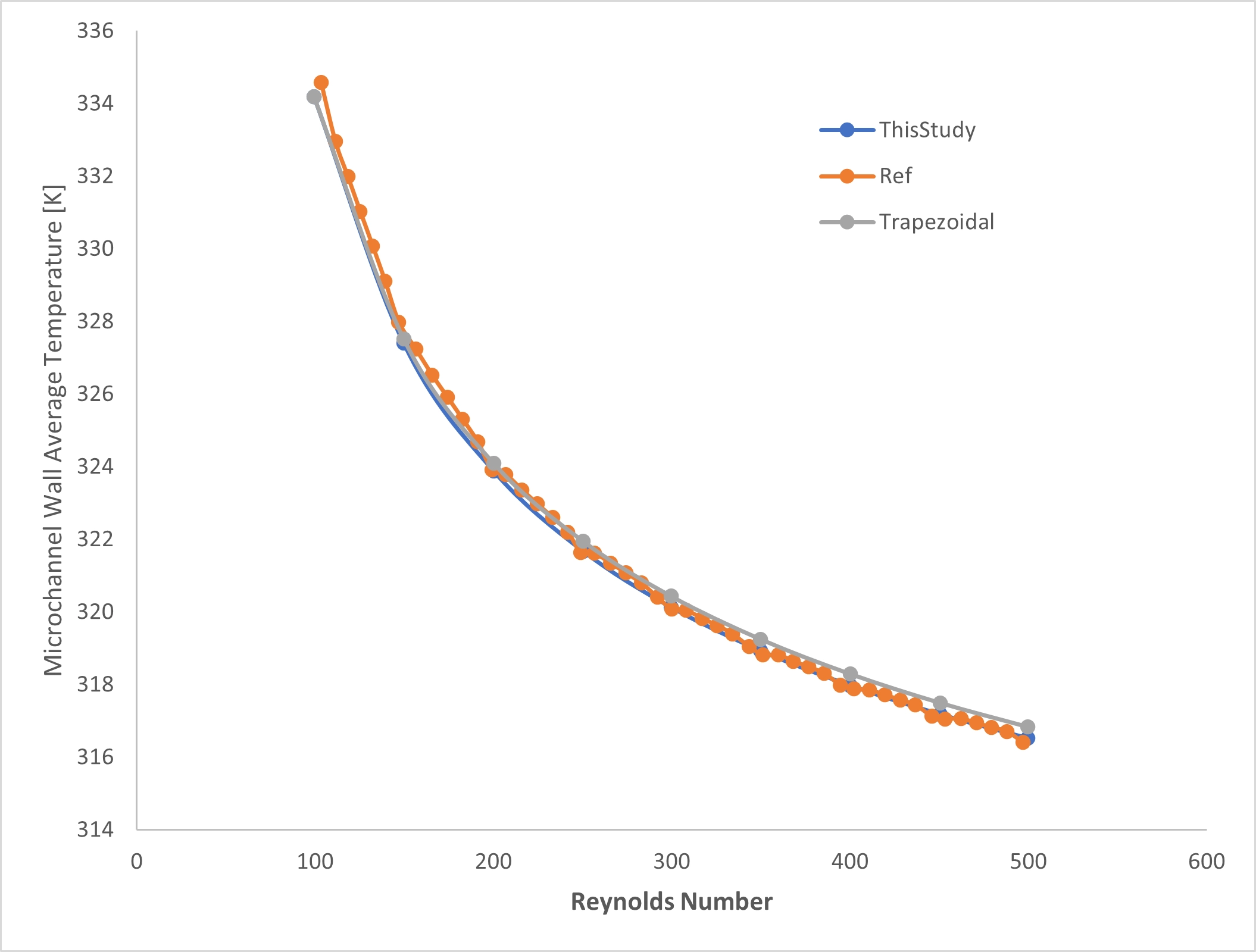
In this section, we look at the results of our Grooved Microchannel Thermal Improvement CFD study. We need to prove that our simulation is correct. First, we look at the Validation Plot (Figure 3). This graph compares our results with the real experiments from the paper. The x-axis shows the Reynolds number (Re), which is the speed of the fluid, from 100 to 550. The y-axis shows the wall temperature in Kelvin.
- The Results: Our result is the blue line (“ThisStudy”). The paper’s result is the orange line (“Ref”). As you can see, the lines sit perfectly on top of each other.
- The Data: At Re=100 (slow flow), the wall is hot, about 334.5 K. As the flow gets faster (Re=550), the wall gets cooler, dropping to 316.5 K. The difference between our CFD simulation and the experiment is less than 1 K. This is an error of only 0.3%. This proves our ANSYS Fluent analysis is very accurate.
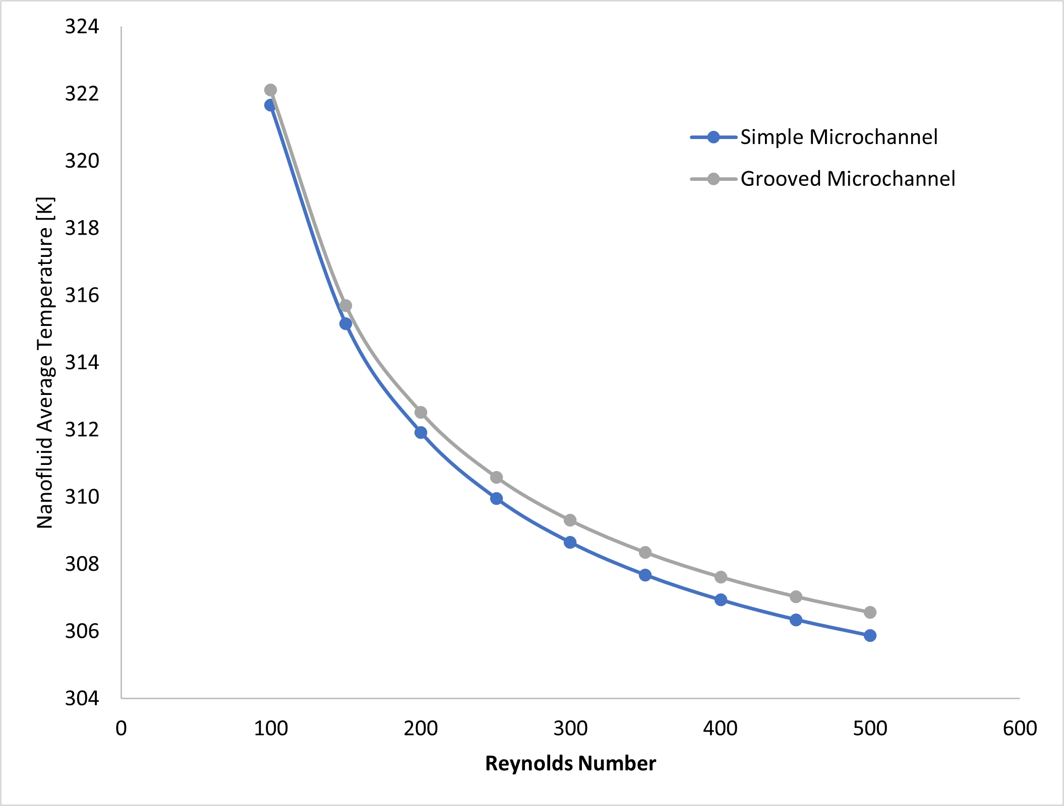
Next, we compare the Grooved vs. Smooth Channel (Figure 4). The blue line is the smooth channel, and the gray line is the grooved channel. The gray line is always lower. This means the grooved channel keeps the fluid cooler. The data shows that the grooved design is about 0.5 K to 1.5 K cooler than the smooth one. This proves that adding grooves really works for thermal improvement.
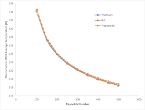
Figure 3: Validation graph showing our ANSYS Fluent CFD results match the reference paper data perfectly.
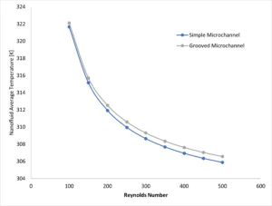
Figure 4: Comparison graph showing the grooved microchannel keeps the nanofluid cooler than the smooth channel.
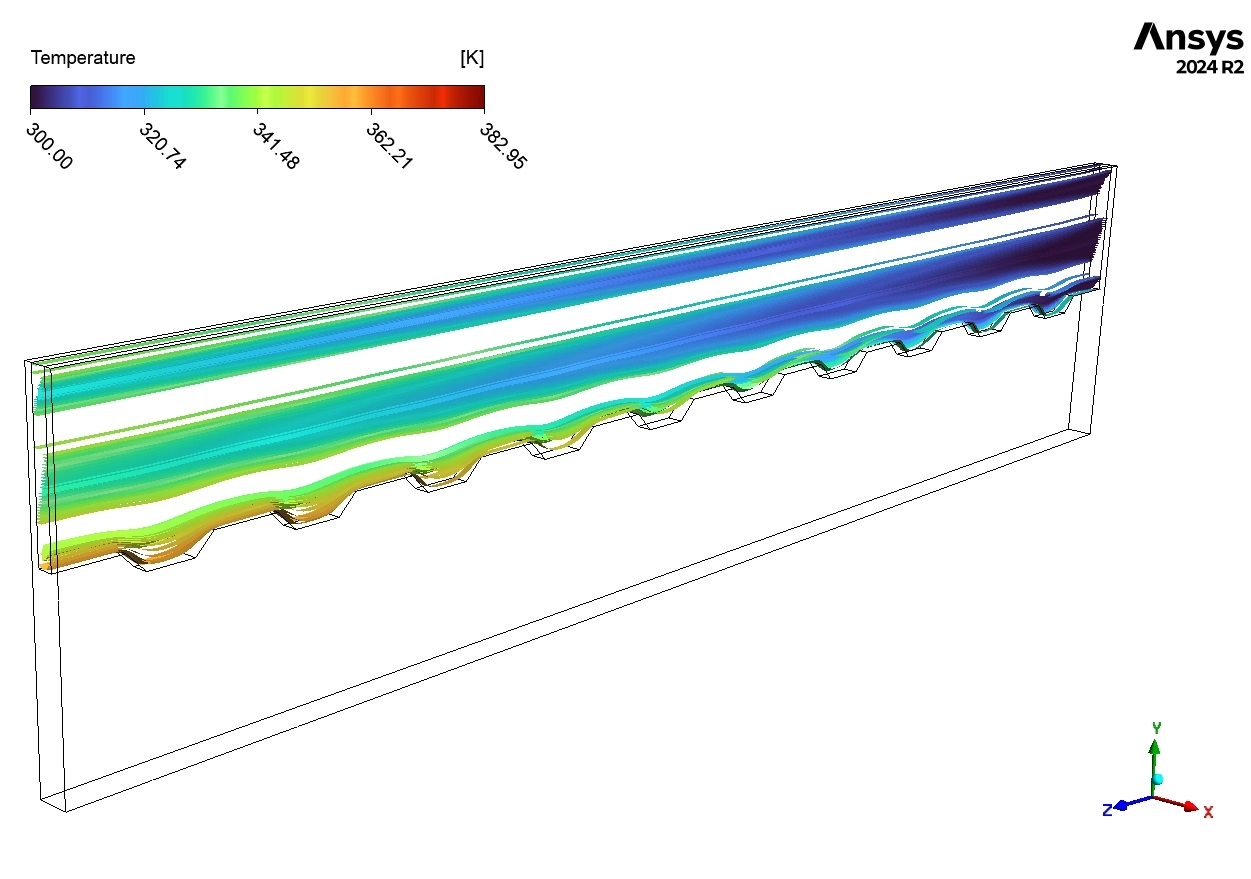
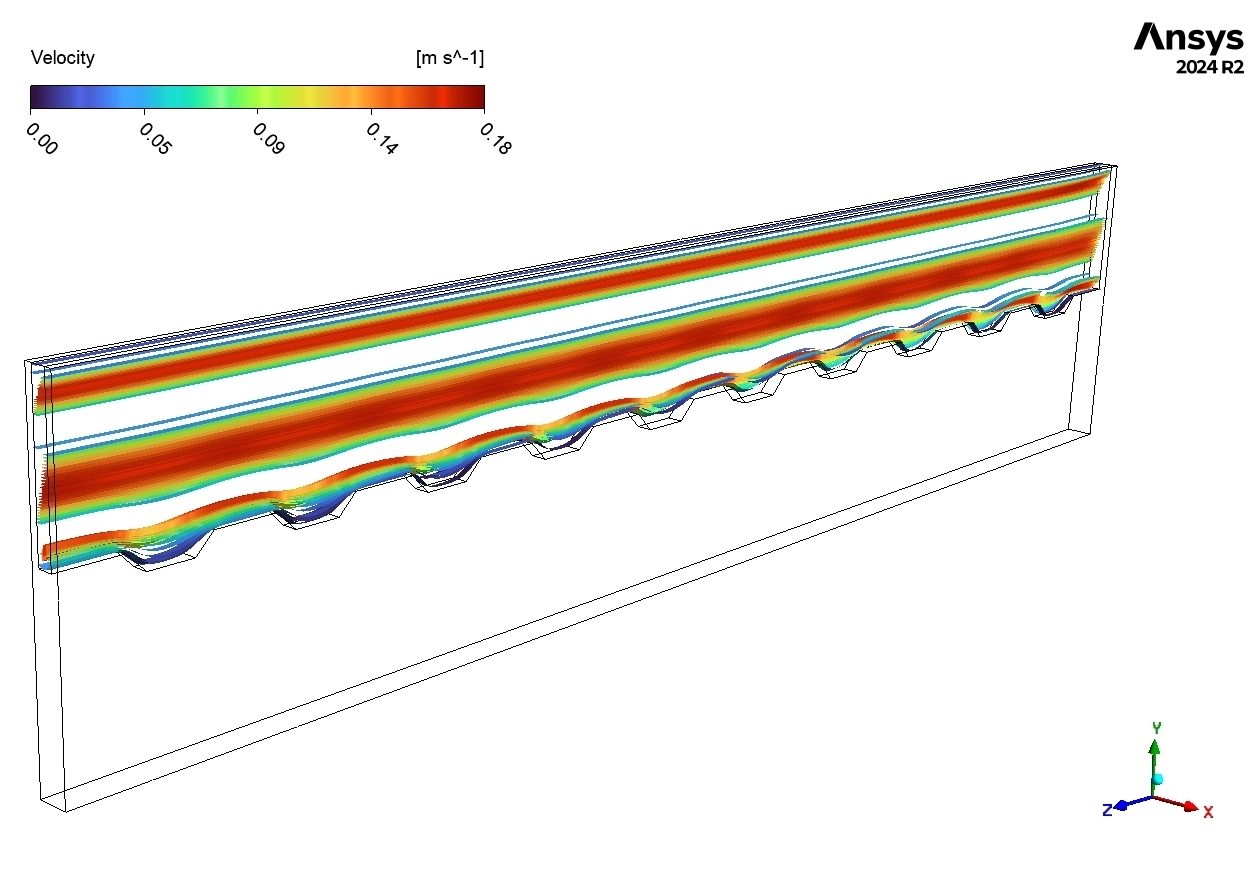
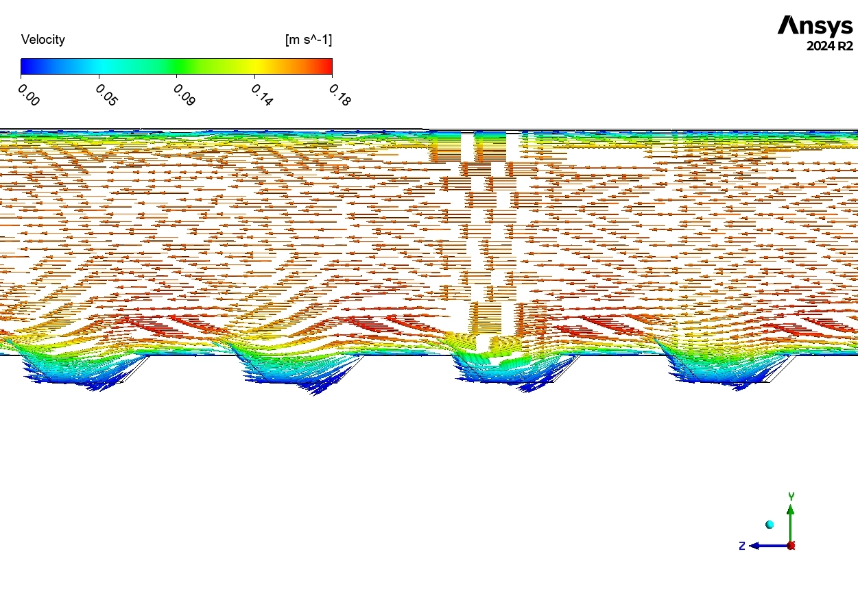
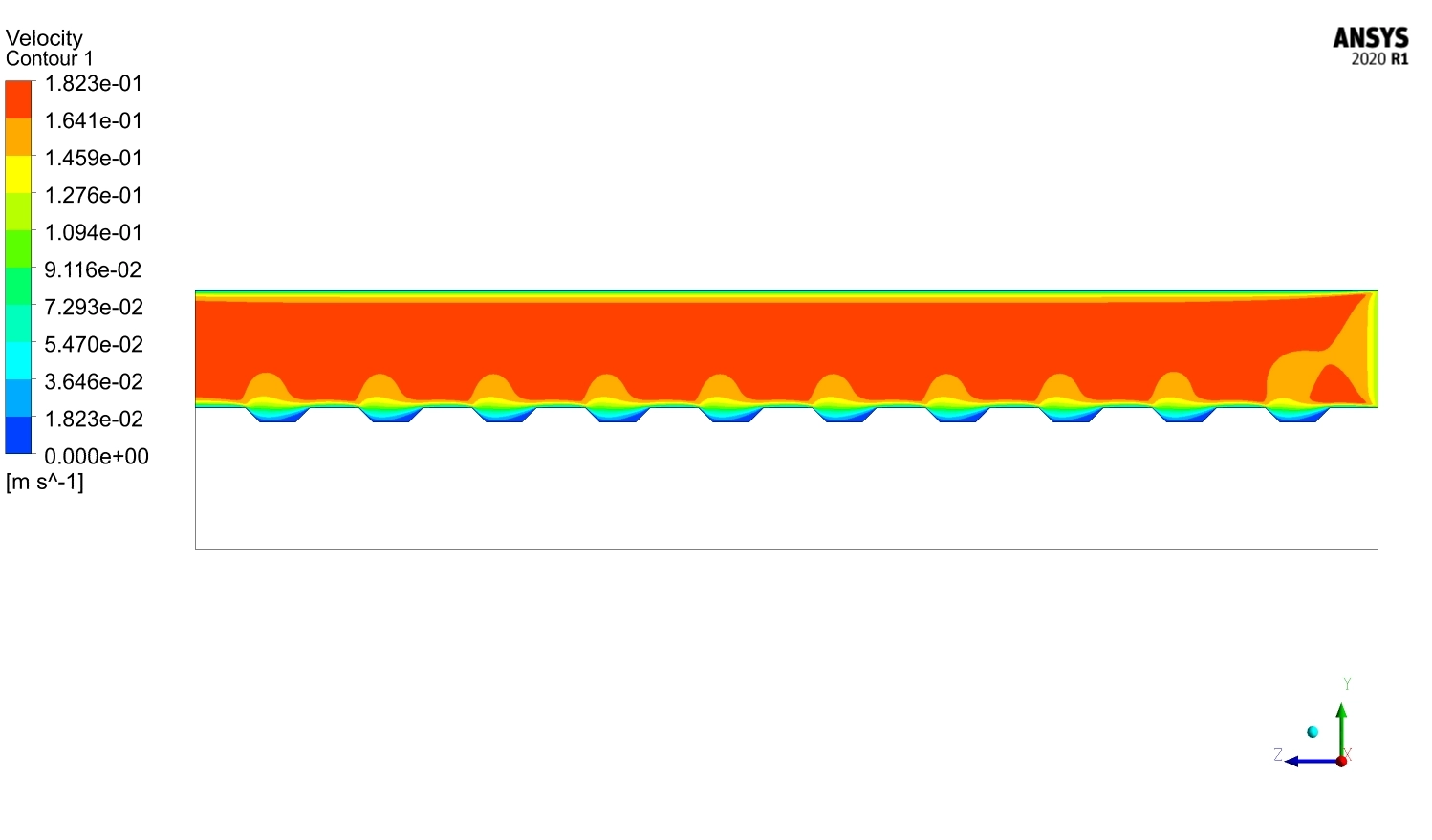
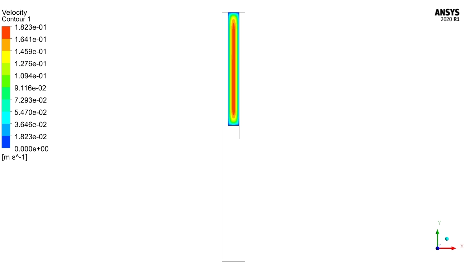
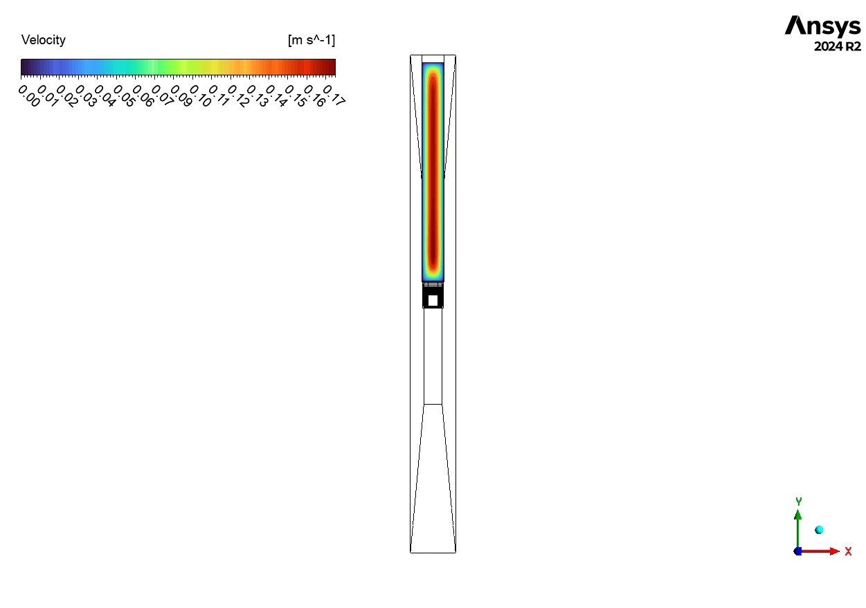
Finally, we look at the pictures of the flow to understand why it works. This is the power of a CFD tutorial. In the Velocity Vector Plot (Figure 6), we can see the side view of the channel. The main flow at the top moves fast, reaching about 0.18 m/s (red color). But look inside the triangular grooves. We see blue curved arrows. These are “vortices” or spinning water. The speed here is low, about 0.00 to 0.08 m/s. This spinning motion is very important. It acts like a spoon stirring coffee. It mixes the hot water near the wall with the cold water in the middle.
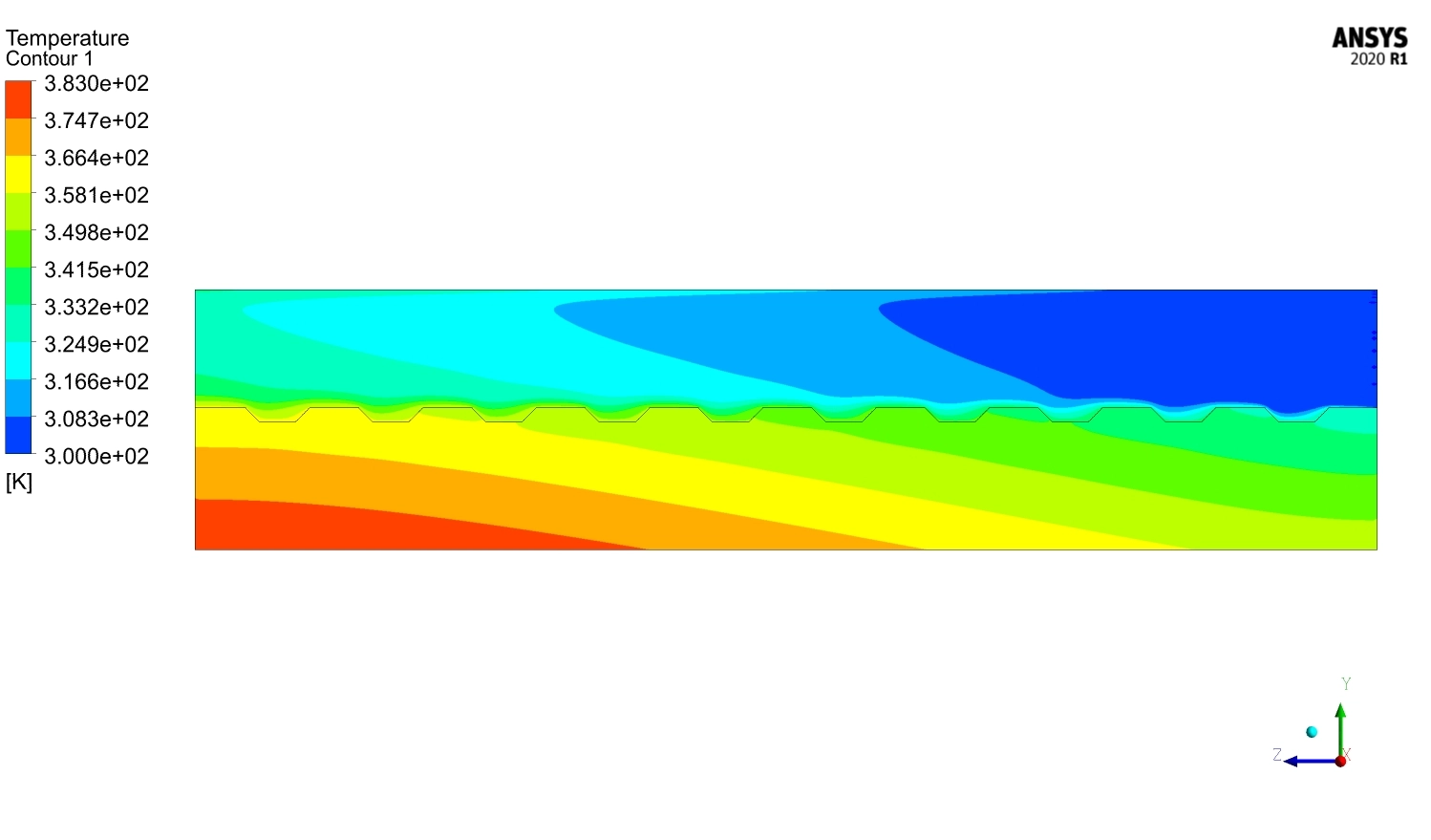
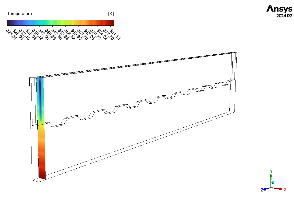
The Temperature Contours (Figure 5 and Figure 7) show the result of this mixing. In the smooth channel, the heat builds up evenly from 300 K to 383 K. The outlet is 83 degrees hotter than the inlet! But in the grooved channel, the temperature lines are wavy. This wavy pattern shows that the grooves are breaking the heat layer. This confirms that our ANSYS Fluent CFD simulation successfully captures the complex physics of microchannel cooling.
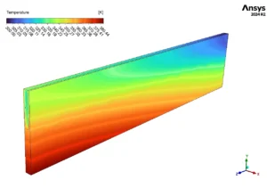

Figure 5: Temperature contour of the smooth channel showing heat building up from inlet (blue) to outlet (red).

Figure 6: Velocity vectors showing spinning vortices inside the grooves which help mix the fluid.
Key Takeaways & FAQ
- Q: What is Grooved Microchannel Thermal Improvement CFD?
- A: It is a computer simulation using software like ANSYS Fluent. It studies how cutting grooves in small cooling tubes helps remove heat from electronics more efficiently.
- Q: Why do we use Nanofluids in this simulation?
- A: Nanofluids are liquids mixed with tiny particles. They are better at carrying heat than regular water. Using them in a CFD analysis gives better cooling results.
- Q: How do the grooves help cool the device?
- A: The grooves create small spinning circles of fluid called “vortices.” These vortices mix the hot and cold liquid together. This mixing lowers the wall temperature, as shown in our ANSYS Fluent tutorial.


Reviews
There are no reviews yet.