

Head loss is the energy that water loses when it moves through pipes. A Head Loss In Pipe Fitting CFD simulation is a very important tool that helps engineers understand this energy loss. When water flows through a pipe fitting, like a tee junction, it has to change direction. This change creates turbulence and friction, which leads to a pressure drop. A Pipe Fitting Fluent analysis helps engineers see exactly where and why this happens. Understanding the head loss coefficient is key for designing good piping systems that do not waste energy. This simulation uses ANSYS Fluent to study the turbulent flow in a tee junction and is inspired by the excellent research paper, “Teaching turbulent flow through pipe fittings using computational fluid dynamics approach” [1].
- Reference [1]: Gajbhiye, Bhavesh D., et al. “Teaching turbulent flow through pipe fittings using computational fluid dynamics approach.” Engineering Reports1 (2020): e12093.
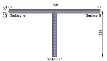
Figure 1: The T-junction pipe fitting geometry used in this Head Loss CFD analysis [1].
Simulation process: Fluent Setup, Grid Independence Study for a Tee Junction
To begin our Pipe Fitting CFD simulation, we followed the setup in the reference paper [1]. A key step for getting accurate results is a grid independence study. We created four different meshes with 72,532, 162,918, 261,270, and 494,266 cells. After testing all four, we chose the grid with 261,270 cells. This mesh was the best because it gave us a stable and correct head loss value without using too much computer time. We then ran the simulation three different times using three different flow speeds, which are defined by Reynolds numbers of 10,000, 15,000, and 20,000. This careful setup in ANSYS Fluent ensures our results are reliable.
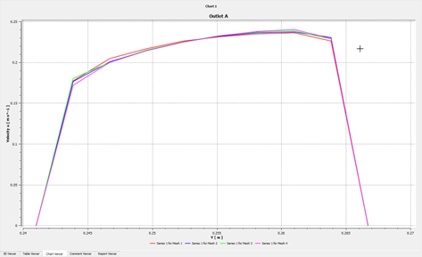
Figure 2: The grid independence study for the Head Loss In Pipe Fitting Fluent simulation.
Post-processing: CFD Analysis, Visualizing Flow Structures and Pressure Drop
The velocity streamlines provide a professional visual of the complex flow inside the tee junction. The professional visual shows that water enters the pipe smoothly but the flow becomes very messy at the corner where the pipes meet. Water reaches a top speed of 0.91 m/s in the straight pipe sections. Right at the junction, we can see the water slowing down and creating large spinning circles, called vortices. These vortices are the main reason why energy is lost. They act like a brake on the flow, turning useful pressure into wasted heat and turbulence.
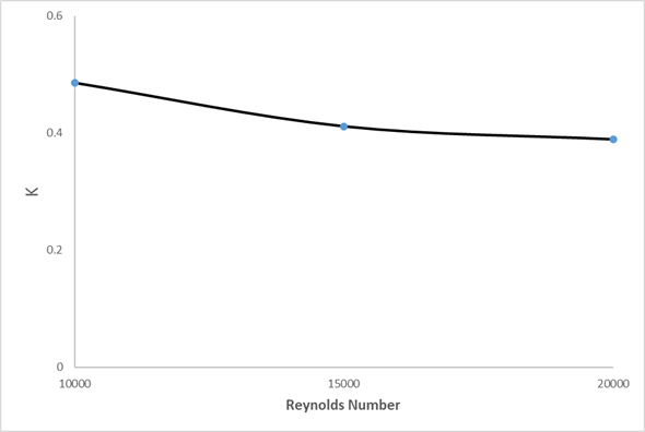
Figure 3: Head loss coefficient Vs. Reynolds number
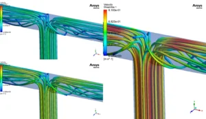
Figure 4: Velocity streamlines and head loss coefficients from the Turbulent Flow in Tee Junction analysis.
The pressure contour tells the rest of the story and shows exactly where this energy is lost. This professional visual shows high pressure at the inlet, with a maximum value of 391.6 Pascals. At the junction corner where the vortices form, the pressure drops sharply, reaching a minimum of -133.4 Pascals. This large pressure drop is the head loss. Our simulation found that the head loss coefficient was 0.486 for the slowest flow and dropped to 0.389 for the fastest flow. This is a total reduction of 19.95%. The most important achievement of this simulation is the clear, visual proof that the size and intensity of the vortices at the junction directly control the amount of energy lost, and that this loss becomes proportionally smaller at higher flow speeds, giving engineers the precise data needed to design more energy-efficient piping systems.
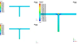
Figure 5: Pressure distribution from the Pressure Drop in Pipe Fittings CFD simulation, showing the location of head loss


Reviews
There are no reviews yet.