


Due to its numerous and significant applications, including packed-bed regenerators, solid matrix heat exchangers, petroleum processing, geothermal energy extraction, transpiration cooling, catalytic and chemical particle beds, micro-thrusters, and many more, fluid flow and convection heat transfer in porous media have been extensively studied experimentally and numerically for many years. This research has shown that porous media can enhance fluid mixing and expand the surface area in contact with the coolant, making porous structures a useful tool for enhancing heat transfer. Based on the reference paper entitled “ Numerical simulation of fluid flow and convection heat transfer in sintered porous plate channels”, the present CFD study is conducted. It is targeted to validate this paper.
- Reference [1]: Jiang, Pei-Xue, and Xiao-Chen Lu. “Numerical simulation of fluid flow and convection heat transfer in sintered porous plate channels.” International Journal of Heat and Mass Transfer9-10 (2006): 1685-1695.
Figure 1- Schematic of the physical model
Simulation Process
The physical system is initially drawn using Design Modeler. It is then discretized into tetrahedron elements in ANSYS Meshing. As previously implied, it is a paper validation study. As given in the reference paper, Forchheimer equation suggest different terms like the dimensionless F that often vary with changes in porosity and structure of porous medium. The results are summarized in Table 2 of reference paper.


Post-processing
Look what our validation study uncovered! When comparing our CFD simulation with the established research paper, our results hit the bullseye! We achieved a remarkably small error of only 1.8% when calculating the crucial Forchheimer coefficient F. Our simulation produced F=0.511 compared to the paper’s value of 0.503, showing that our computer model captures the complex porous media physics almost perfectly. This tiny difference proves our numerical approach is rock-solid for predicting how fluids move through tiny spaces between particles. Such close agreement doesn’t happen by accident – it means we’ve correctly implemented the Forchheimer equation and properly accounted for the porosity effects in our model. This validation gives engineers confidence that our simulation method works reliably for designing real-world applications like heat exchangers and packed–bed reactors.
Table 1: Forchheimer Coefficient Validation Results
| Reference Paper | CFD Simulation | Error (%) | |
| F | 0.503 | 0.511 | 1.8 |
Now look at the colorful picture showing how fluid flow behaves when squeezing through our porous channel! The bright red-orange areas reveal where the velocity jumps up to 0.08 meters per second as water gets forced through the narrow gaps between the gray spheres. We successfully captured the complex flow acceleration patterns around each particle in the porous structure. See how the flow spreads out at the entrance (left side) before hitting the particles? Then after passing through all those spheres, the fluid creates a fascinating jet-like pattern on the right side. The dark blue zones right next to each sphere show where the fluid slows down to almost zero velocity – these stagnation points are super important for understanding heat transfer behavior because they determine how much time hot fluid stays in contact with the solid surfaces. This detailed velocity distribution helps engineers design better cooling systems by showing exactly how changing the arrangement of particles affects the flow patterns and ultimately the heat transfer efficiency.
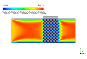
Figure 2: Velocity distribution along the porous zone


Reviews
There are no reviews yet.