

Hydrogen is widely considered a highly clean fuel because it primarily produces safe water vapor when it burns with air. However, the exact physics of Hydrogen-air Combustion happen at extremely high temperatures. This intense heat creates two dangerous challenges for industrial engineers. First, a massive amount of invisible energy is transferred by radiation, which can easily melt or destroy the solid walls of the burner. Second, the extreme temperatures force the natural nitrogen gas from the air to react, causing dangerous thermal NOx formation.
To perfectly understand these complex flow physics and chemical reactions, engineers perform a highly accurate 3D combustion CFD simulation of a micro-cylindrical combustor. This computational representation is guided by famous scientific studies, such as the research by Pashchenko and Jiaqiang. By exploring this Ansys Fluent tutorial project, designers can safely evaluate the environmental impact of the burner without building expensive prototypes. To learn more about how powerful software calculates intense fire and toxic gases, please explore our professional Combustion engineering category.
- Reference [1]: Pashchenko, Dmitry. “Comparative analysis of hydrogen/air combustion CFD-modeling for 3D and 2D computational domain of micro-cylindrical combustor.” International Journal of Hydrogen Energy49 (2017): 29545-29556.
- Reference [2]: Jiaqiang, E., et al. “Effects of inlet pressure on wall temperature and exergy efficiency of the micro-cylindrical combustor with a step.” Applied Energy175 (2016): 337-345.
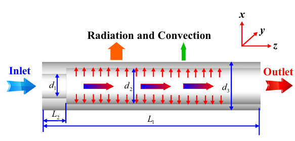
Figure 1: A schematic diagram showing the exact design and boundary dimensions of the micro-cylindrical combustor based on Jiaqiang’s reference.
Simulation Process: Species Transport and Chemkin Mechanism CFD Setup
Creating a mathematically stable simulation requires a very careful geometry and mesh setup. For this project, we built the 3D geometry of the micro-combustor using exactly 26 separate bodies. This smart multi-body approach allowed the software to generate a flawless, fully structured mesh containing exactly 164,160 cells. A structured mesh is absolutely required to prevent mathematical errors when solving complex reacting flows.
Inside ANSYS Fluent, we activated the Species Transport model to calculate the gas chemistry. To guarantee maximum accuracy, we used the famous Chemkin mechanism to program exactly 19 separate chemical reactions into the fluid solver. Because the hydrogen flame generates extreme heat, we also activated the P1 radiation model. Furthermore, we enabled the dedicated NOx Model to mathematically track the harmful pollutants forming in the air.

Figure 2:
The complete 3D geometry of the combustion chamber, uniquely composed of 26 separate bodies to allow for perfect mesh control.

Figure 3: The high-quality structured mesh containing exactly 164,160 cells, used to provide a highly stable solution for the complex 3D Combustion Chamber Simulation.
Post-processing: Analysis of Flame Structure and Pollutants
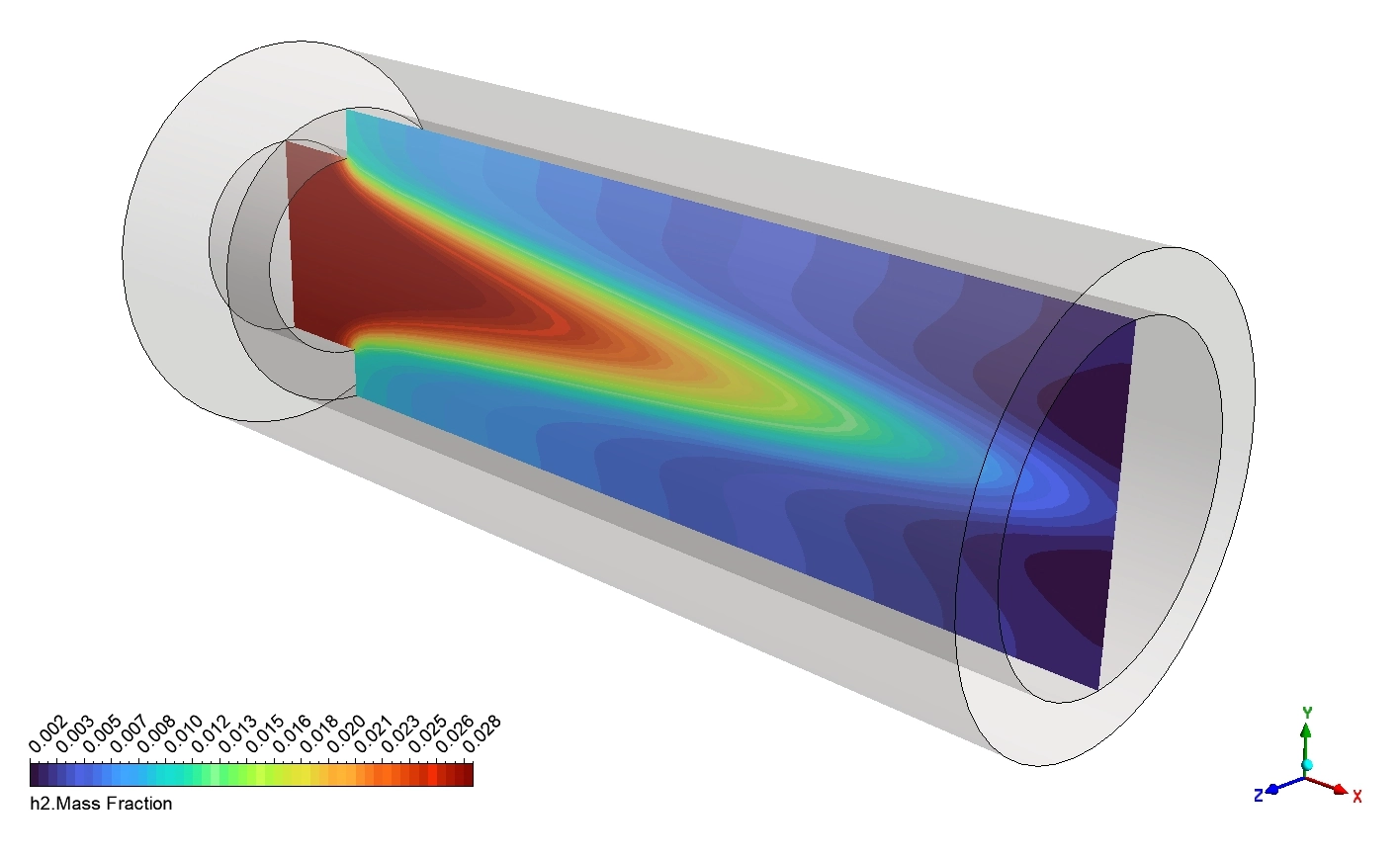
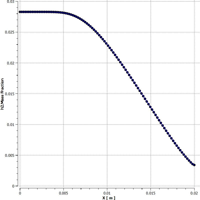
To understand the exact physical behavior of the burner, we must carefully read the mathematical visual data. The unburned hydrogen gas enters the micro-cylinder with a starting mass fraction of exactly 0.028. Based on the provided X-axis line plot, this fuel travels forward smoothly until it reaches a distance of 0.005 meters. At this exact location, the intense chemical burning abruptly begins. Consequently, the hydrogen is rapidly eaten by the fire, dropping the fuel mass fraction down to a very low 0.003 at the exit (x = 0.02 m). The colorful mid-plane contour perfectly matches this chart, displaying a distinct V-shaped blue and green zone where the fuel completely disappears.
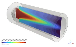
Figure 1: Mid-plane contour of H2 Mass Fraction, displaying the clear V-shaped boundary where the hydrogen fuel is consumed.
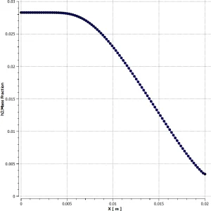
Figure 2: Plot of H2 Mass Fraction along the X-axis, showing the sudden drop from 0.028 to 0.003 starting exactly at x = 0.005 m.
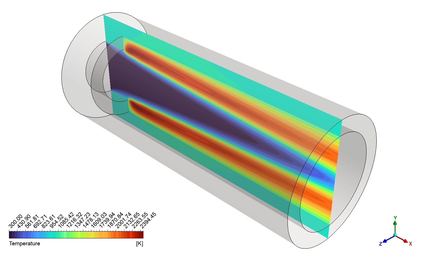
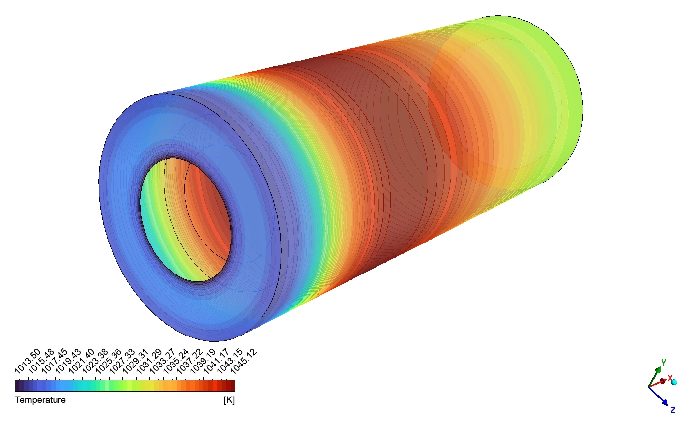
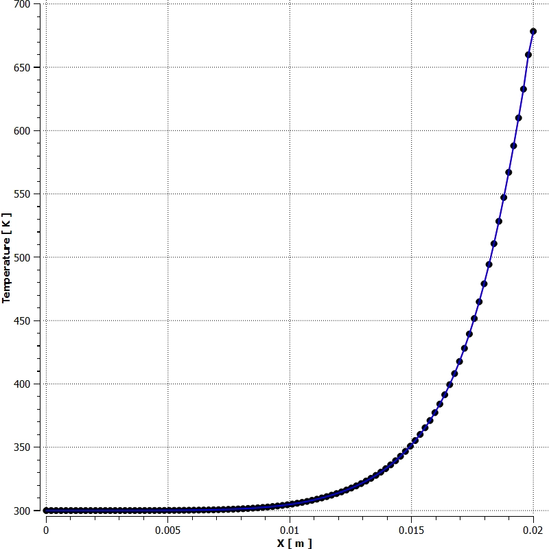
This rapid fuel consumption creates massive thermal energy. The temperature contour reveals that while the cold inlet air starts at 300 K, the main fire front erupts into a bright red V-shape, hitting an extreme maximum heat of exactly 2394.45 K. Interestingly, the centerline plot proves that the exact middle of the tube remains relatively cold for a long time. The center axis stays at 300 K until x = 0.01 m, and only rises to roughly 670 K by the end of the tube. Moreover, the extreme internal flame radiates heavy heat outward to the solid boundaries. The outer surface temperature contour shows the external wall warming up smoothly from 1013.50 K to a peak of 1045.12 K.
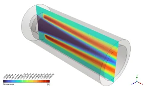
Figure 3: Mid-plane Temperature contour (300 K to 2394.45 K), revealing the extreme red V-shaped flame front inside the cylinder.
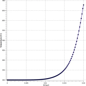
Figure 4: Centerline Temperature plot along the X-axis, proving the middle axis remains at 300 K until x = 0.01 m before rising to 670 K.
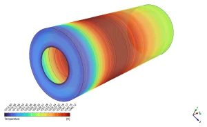
Figure 5: Outer Wall Temperature contour (1013.50 K to 1045.12 K), showing how the intense internal radiation heats the exterior surface.
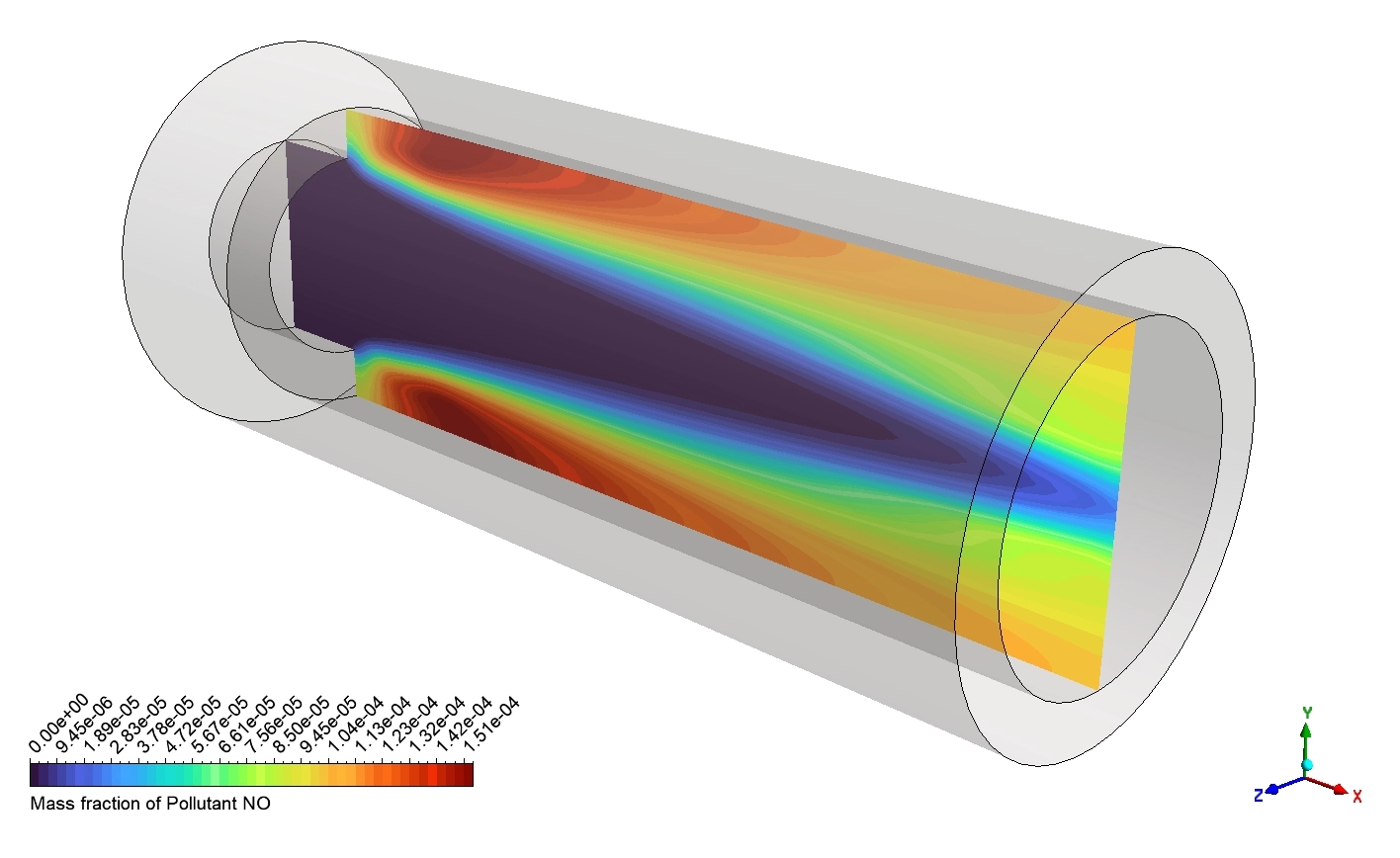
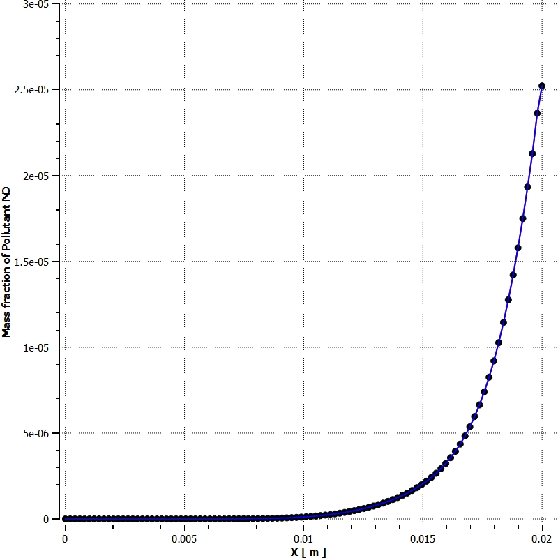
This extreme 2394.45 K internal flame causes a serious environmental problem. The high heat forces the nitrogen to react, creating toxic pollution. The Pollutant NO mass fraction contour visually proves this physics. The red pollution zones appear exactly in the same V-shape as the hottest fire, hitting a local maximum concentration of 1.51e-04. To measure the total pollution produced by the whole machine, the software calculated the mass-weighted average for the entire fluid volume. The exact mathematical output is a NO mass fraction of 5.7522941e-05. This vital number proves that harmful gas successfully forms, meaning designers must adjust the air-fuel mixture to lower the peak heat and protect the environment.
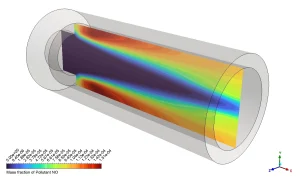
Figure 6: Mid-plane contour of Pollutant NO mass fraction, illustrating how the toxic gas (up to 1.51e-04) forms perfectly along the hottest 2394 K regions.
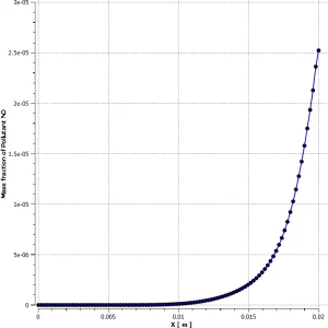
Figure 7: Pollutant generation through the combustor centerline
Frequently Asked Questions (FAQ)
- Why does the centerline temperature stay cool for so long?
- The centerline stays at 300 K until x = 0.01 m because the chemical fire starts at the outer edges of the mixing zone, creating a V-shape. The cold, unburned gases remain trapped inside the middle of this V-shape before they finally heat up near the exit.
- Why is a structured mesh of 164,160 cells important?
- Chemical burning using a 19-step Chemkin mechanism requires massive mathematical calculations. A structured mesh has perfectly aligned, square-like cells that help the software solve these complex equations smoothly without crashing.
- How does the P1 radiation model affect the outer wall temperature?
- The P1 model calculates how invisible heat rays shoot away from the 2394.45 K flame. These rays strike the inside of the metal wall, successfully heating the entire solid exterior to roughly 1045.12 K.







Reviews
There are no reviews yet.