
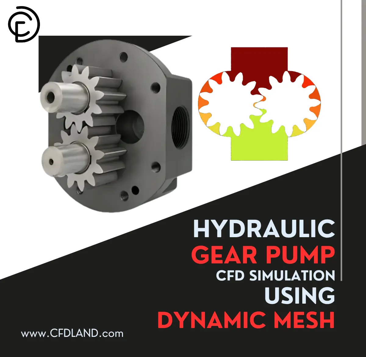
Hydraulic gear pumps are positive displacement pumps that use rotating gears to move fluid from inlet to outlet at high pressures. The most common type is the external gear pump, where two meshing gears rotate in opposite directions to trap and push fluid through the pump housing. Gear pump CFD analysis helps engineers understand exactly how these pumps achieve flow rates ranging from 1 to 1500 liters per minute and pressure outputs up to 300 bar. When gears rotate inside a hydraulic gear pump, they create expanding volumes at the inlet (suction) and shrinking volumes at the outlet (discharge), which generates the pumping action. Gear pump Fluent simulations using dynamic mesh technology can accurately track how gear teeth engagement affects volumetric efficiency, typically 85-95% for well-designed pumps. The pump displacement (volume moved per revolution) depends on gear dimensions, tooth profile, and clearances between moving parts. Internal gear pumps work similarly but use one gear inside another, offering smoother flow with less pulsation. Hydraulic pump CFD models reveal important details like pressure ripple, cavitation risks, and leakage paths that affect overall pump performance. Understanding gear pump simulation requires modeling the complex interaction between rotating gears, fluid properties, and small clearances (typically 0.01-0.15mm). ANSYS Fluent gear pump models with dynamic mesh can predict actual flow characteristics, mechanical efficiency, and optimal operating speeds for different hydraulic fluids.
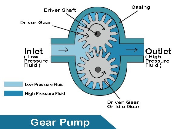
Figure 1: Schematic of hydraulic gear pump and how it works
Simulation Process of Hydraulic Gear Pump Fluent CFD
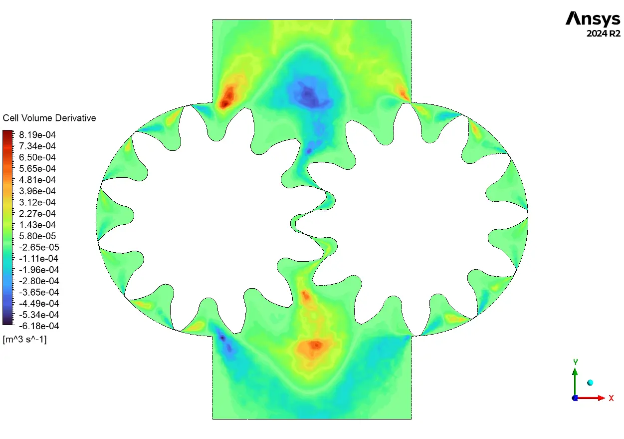
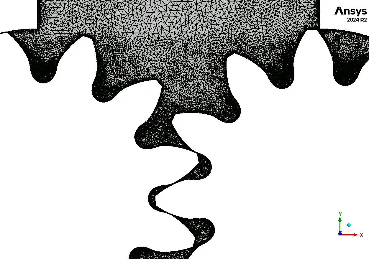
The 2D gear pump geometry was created to capture the essential rotating motion of both gears while keeping computational time reasonable. We used triangular cells throughout the fluid domain because they adapt better to the constantly changing shape as gear teeth mesh and unmesh during rotation. The Dynamic Mesh feature in ANSYS Fluent is essential for this gear pump CFD simulation since the fluid domain changes shape every time step as gears rotate. Running this as a transient simulation allows us to track how flow rate and pressure vary during each revolution of the hydraulic gear pump. The smoothing method helps maintain good mesh quality by adjusting node positions when cells get distorted near the meshing gear teeth. Remeshing automatically replaces poor quality cells with new ones when smoothing alone cannot maintain acceptable cell shapes. This combination of dynamic mesh techniques ensures the gear pump Fluent model remains stable and accurate throughout the full rotation cycle. The CFD setup captures the small clearances between gear tips and housing wall.
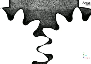
Figure 2: Triangle cells in the initial step before remeshing
Post-processing of Hydraulic Gear Pump CFD Analysis
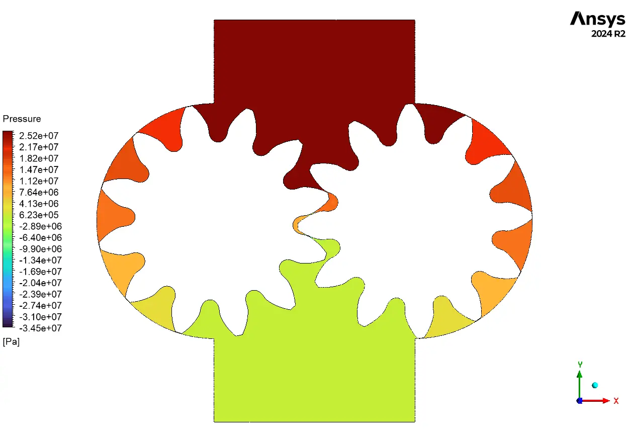
The pressure distribution perfectly illustrates how gear pumps generate their pumping power, with outlet pressure reaching 25.2 MPa (252 bar) while inlet shows vacuum conditions down to -34.5 MPa. This enormous 59.7 MPa total pressure differential drives the fluid through the system and represents typical operating conditions for high-pressure hydraulic gear pumps. Each gear tooth acts like a moving barrier that compresses fluid on the discharge side while creating suction on the inlet side. The gear pump Fluent analysis reveals smooth pressure transition from negative (suction) to positive (discharge) values as fluid travels around the gears. Peak pressures occur right at the meshing zone where teeth squeeze out trapped fluid, explaining why gear pump design must carefully balance clearances to prevent excessive leakage while avoiding metal contact. The simulation confirms this hydraulic pump CFD model achieves realistic pressure ripple patterns that match the number of teeth, validating our dynamic mesh approach for predicting pump performance. These results prove that gear pump simulation can accurately predict both instantaneous and average flow characteristics needed for optimizing pump efficiency and reducing pressure pulsations.

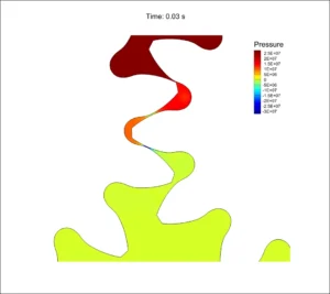
Figure 3: Pressure Distribution in Hydraulic Gear Pump
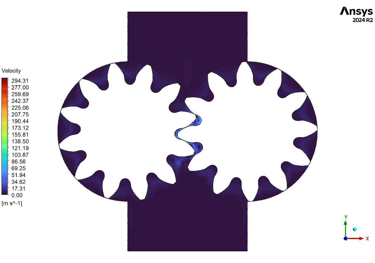
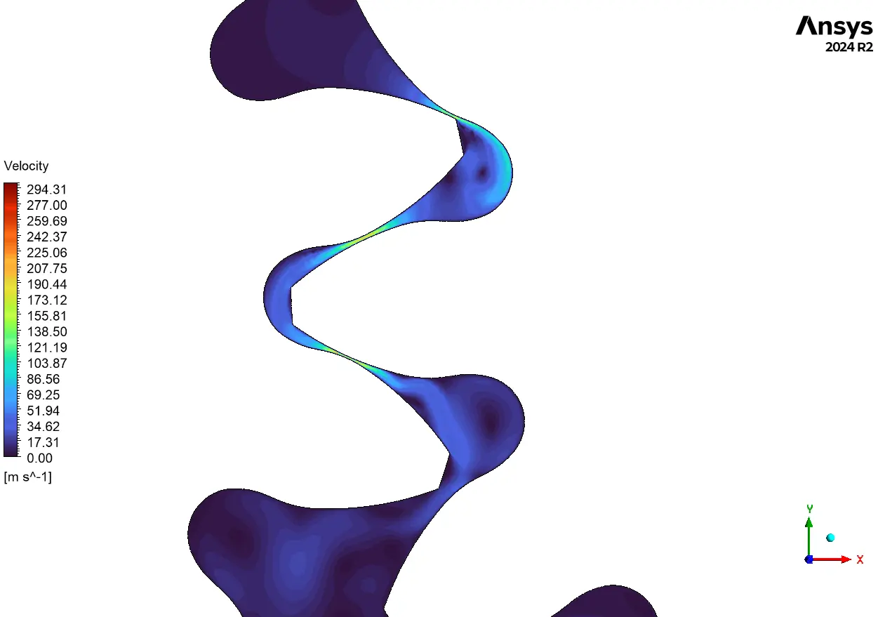
The velocity field inside the hydraulic gear pump reaches extreme values of 294.31 m/s at the narrowest gaps between meshing teeth, where fluid gets squeezed through tiny clearances. These high-speed jets occur when trapped fluid volumes suddenly connect with adjacent chambers, creating the characteristic pulsating flow of external gear pumps. The gear pump CFD results demonstrate smooth acceleration from near-zero velocity in trapped pockets to moderate speeds of 50-100 m/s in the main flow channels. This velocity pattern confirms proper pumping action as each tooth pocket carries fluid from inlet to outlet at speeds proportional to the gear rotation rate. The ANSYS Fluent simulation captures how velocity gradually builds up along the gear periphery, validating the positive displacement principle that makes hydraulic pumps so effective.

Figure 4: Velocity Distribution in Hydraulic Gear Pump


Reviews
There are no reviews yet.