


Microjet Flame combustion focuses on flames generated from extremely small nozzles, typically less than a millimeter in diameter. These tiny flames are vital for modern technology, including micro-thrusters for satellites, portable power generators, and micro-sensors. In a Non-premixed Microjet Flame, the fuel and the oxidizer (air) enter the chamber separately. They only mix and burn after leaving the nozzle. The stability of these flames depends heavily on the detailed chemical reactions that happen at very small scales.
To simulate this accurately, standard models are often insufficient. A high-fidelity Microjet Flame ANSYS Chemkin analysis requires Detailed Chemical Kinetics. This means simulating hundreds of intermediate reactions rather than just one simple step. This project demonstrates a Microjet Flame CFD simulation using ANSYS Fluent. We utilize a CHEMKIN mechanism file to import the full reaction library for the fuel mixture. For more comprehensive guides on reacting flows, please refer to our Combustion Tutorials. The simulation setup is based on the experimental data found in the reference paper by Li et al. [1].
- Reference [1]: Li, Xing, et al. “Combustion characteristics of non-premixed methane micro-jet flame in coflow air and thermal interaction between flame and micro tube.” Applied thermal engineering112 (2017): 296-303.
- Reference [2]: Colson, Sophie, et al. “Stabilization mechanisms of an ammonia/methane non-premixed jet flame up to liftoff.” Combustion and Flame234 (2021): 111657.
![Experimental images of microjet flames from the reference paper [1], showing changes in flame shape with fuel velocity.](https://cfdland.com/wp-content/uploads/2024/04/Picture1-2.png)
Figure 1: Experimental images of microjet flames showing flame shape variations.
Simulation Process: Chemkin Mechanism in ANSYS Fluent
The simulation process began with creating a 2D axisymmetric geometry in ANSYS Design Modeler. Because the microjet is cylindrical, simulating a 2D slice saves significant computational time while maintaining high accuracy. We generated a high-quality structured mesh. The grid was refined heavily near the tiny nozzle exit and the reaction zone. This is necessary to capture the sharp gradients in temperature and species concentration that occur in Microjet Flame combustion.
The core of this Chemkin Fluent simulation was the solver configuration. We enabled the Species Transport model to track the chemical components. The most critical step was the Chemkin mechanism integration. Instead of using a simplified “global” reaction, we imported a detailed chemical kinetic mechanism file directly into ANSYS Fluent. This file contains the complete list of elementary reactions for the fuel (in this case, involving Methane and Ammonia species as per Reference [2]). This allows the solver to calculate the flame speed and structure based on realistic chemistry. The Eddy Dissipation concept was also considered to account for turbulence-chemistry interaction.

Post-Processing: Detailed Chemical Kinetics Analysis
In this section, we analyze the fluid dynamics and thermal structure of the Microjet Flame CFD results. First, we examine the Velocity Magnitude contour in Figure 2. The simulation captures a distinct high-speed jet issuing from the central nozzle. The maximum velocity at the core is 2.80 m/s. This central jet is responsible for carrying the fuel into the chamber. As the jet moves downstream, it slows down because it shears against the stationary surrounding air, creating a mixing layer. Next, we analyze the fuel distribution using the Ammonia (NH3) Mass Fraction contour. The results show that the fuel is highly concentrated in the center of the jet, with a peak mass fraction of 0.535 (or 53.5%). The contour clearly shows the fuel diffusing radially outward. This “mixing” is the most important part of a non-premixed flame. The fuel must physically travel from the rich core to the outer layer to find oxygen.
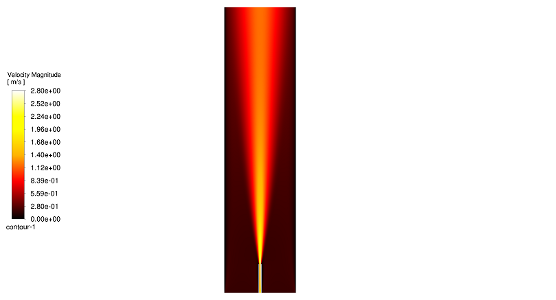
Figure 2: Velocity magnitude contour showing the central fuel jet reaching 2.80 m/s.
Finally, the Static Temperature contour in Figure 3 reveals the true structure of the flame. We see a classic “V-shaped” flame front. The maximum temperature reaches approximately 1960 K. A critical observation from this Chemkin mechanism analysis is the location of this heat. The core of the jet is relatively cool. The peak temperature is located on the flanks or edges of the jet. This is because the core is too rich in fuel to burn. The combustion happens in the thin layer on the outside where the fuel and air mix in the perfect “stoichiometric” ratio. This precise prediction of the flame location is only possible because we used Detailed Chemical Kinetics in ANSYS Fluent.
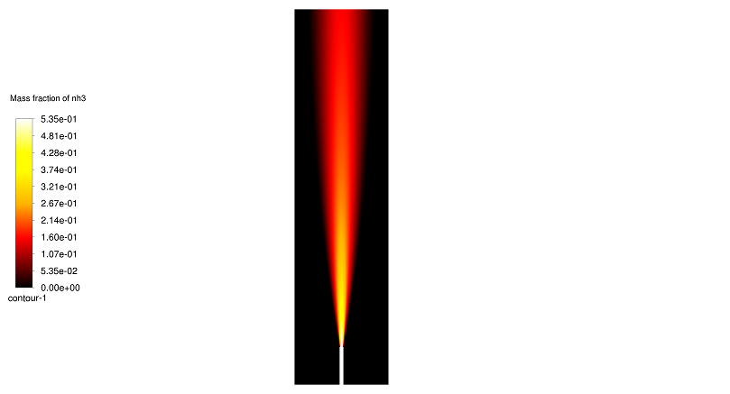
Figure 2: Mass fraction of NH3 fuel, illustrating its high concentration in the jet core before it mixes with the surrounding air. 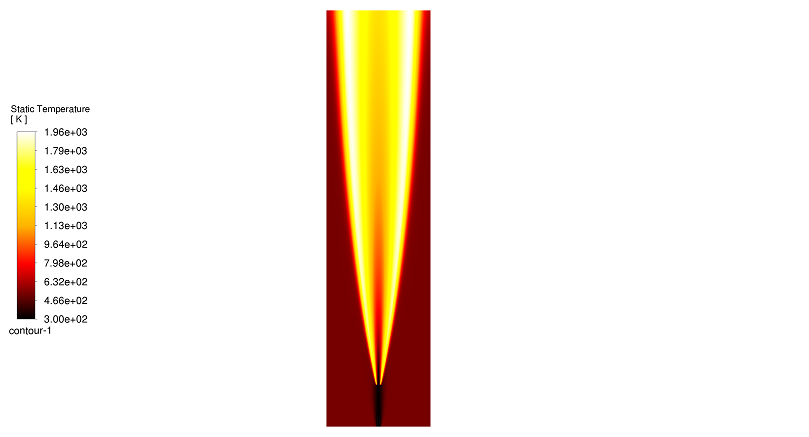
Figure 3: Static temperature contour highlighting the V-shaped flame front and peak temperature of 1960 K.
Key Takeaways & FAQ
- Q: What is a CHEMKIN mechanism in ANSYS Fluent?
- A: A CHEMKIN mechanism is a data file that contains a detailed list of chemical species and elementary reactions (often hundreds of them) along with their reaction rates. Importing this into ANSYS Fluent allows for a much more accurate simulation of combustion compared to simple one-step reaction models.
- Q: Why is the core of the Microjet Flame cooler than the edges?
- A: In a non-premixed flame, the fuel is in the center and the air is on the outside. The center is “fuel-rich” and lacks oxygen, so it cannot burn. The flame only exists on the outer boundary (the reaction zone) where the fuel and air mix in the correct stoichiometric ratio, creating the peak temperature of 1960 K.
- Q: What is the advantage of a Microjet Flame?
- A: Microjet flames are very stable and can be controlled precisely. Their small size makes them ideal for micro-power generation and micro-propulsion systems where space and weight are limited.


Reviews
There are no reviews yet.