


A parallel flow shell and tube heat exchanger (HE) is a basic thermal device in which both fluids (shell-side and tube-side) flow in the same direction. It has its own temperature gradient profile and ways of transferring heat. Key parameters like Reynolds number (Re), heat transfer coefficient (h), pressure drop (ΔP), and overall heat transfer rate (Q) must be carefully thought through in ANSYS Fluent Computational Fluid Dynamics (CFD) simulation in order to get correct results. Important design factors include tube arrangement (square or triangular pitch), baffle spacing, shell diameter, and tube measurements. These all have a big effect on the thermal-hydraulic performance. The parallel flow configuration has some benefits, like being easier to maintain and simpler to make. However, it is usually less thermally effective than counter-flow configurations because the temperature difference decreases along the flow direction. This study is one of the ANSYS Fluent Course For Beginners` session. The intriguing point is that the copper tube`s walls are simulated, showing Conjugate heat transfer.
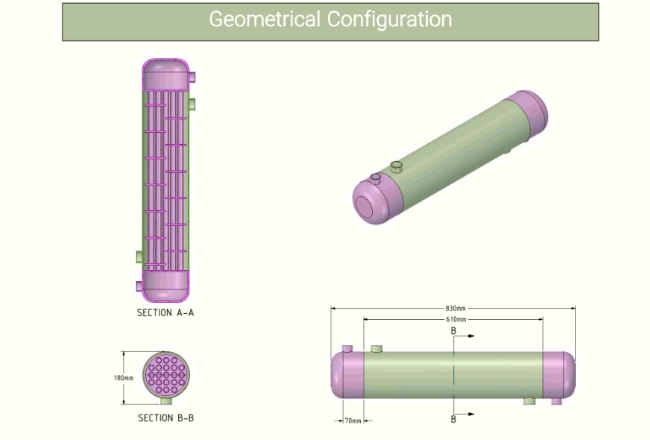
Figure 1: Geometrical configuration of Parallel Flow In Shell & Tube Heat Exchanger
Simulation Process
The simulation process started with carefully designing the heat exchanger geometry in ANSYS Design Modeler. This included important parts like baffles to control the flow direction, end caps to keep the fluid inside, a cylindrical shell housing, and tubes inside arranged in a parallel arrangement. Copper was chosen as the material for the tube walls so that heat could move easily between fluids. Hot water at 393K flowed through the shell side of the model, while cold water at 293K moved through the tube bundle. This was done to show conjugate heat transfer occurrences. For spatial discretization, the computational domain was first meshed using tetrahedron elements in ANSYS Meshing. After that, these tetrahedral elements transformed into polyhedral elements in ANSYS Fluent. This made the computations much faster while keeping the accuracy of the answer.
Post-processing
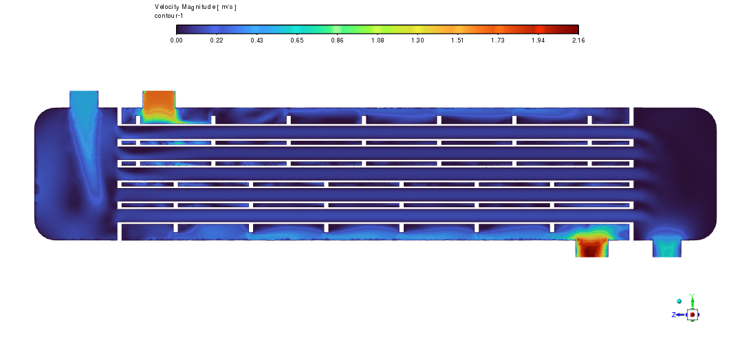
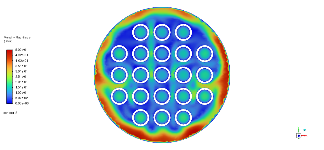
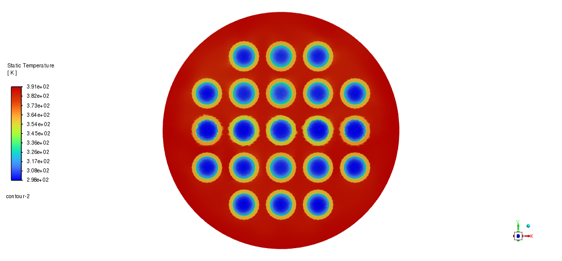
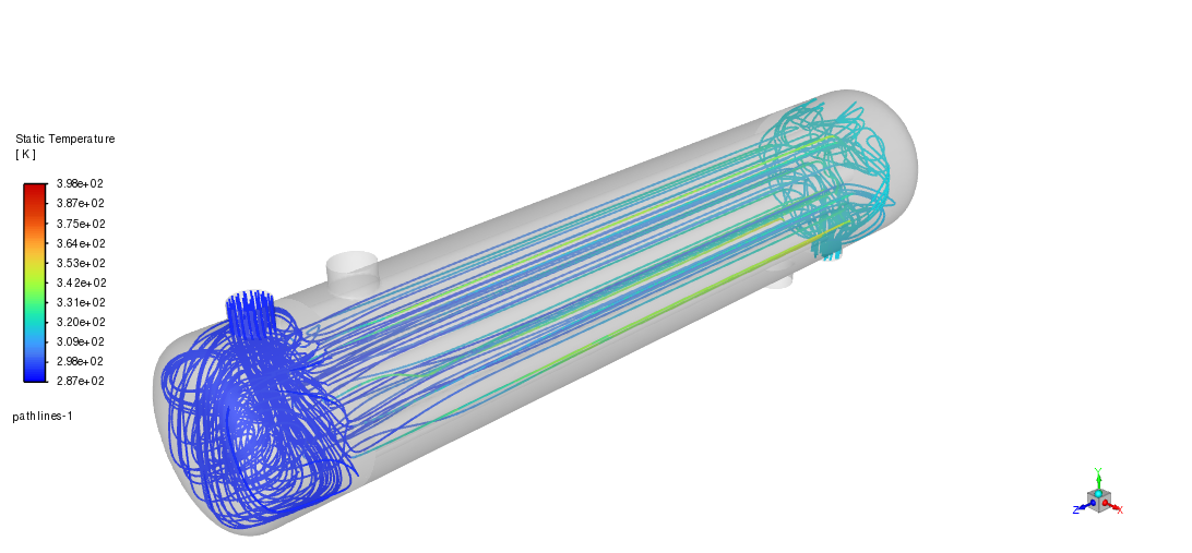
Important elements of the thermal-hydraulic behavior of the heat exchanger are revealed by flow visualization and temperature distribution patterns. Although the blue streamlines in the first figure suggest notable mixing in the inlet area, which is advantageous for heat transfer, this results in a larger pressure drop. From the shell side (red, 393K) to the tube core (blue, ~293K), the temperature contours across the tube bundle shown in the cross-sectional view clearly show a radial temperature gradient, so indicating effective heat transfer across the copper tubes. The second picture shows this pattern especially clearly: the concentric temperature rings surrounding each tube show the formation of thermal boundary layers and the increasing heat transfer from the hot shell-side fluid to the cold tube-side fluid.
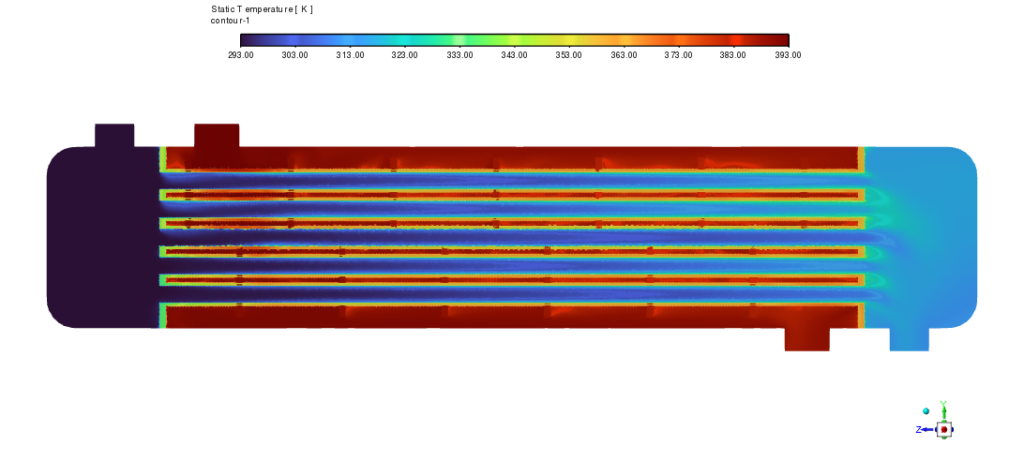
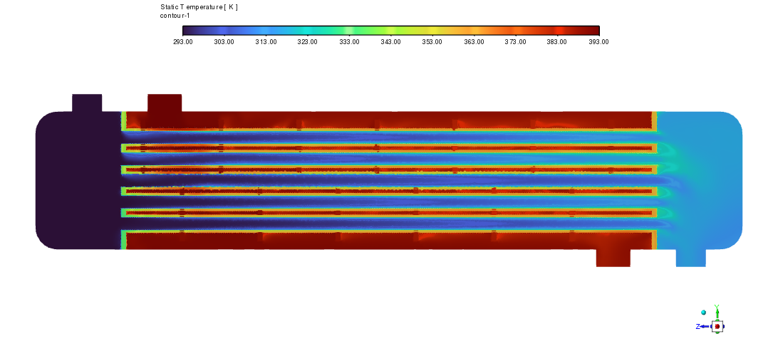
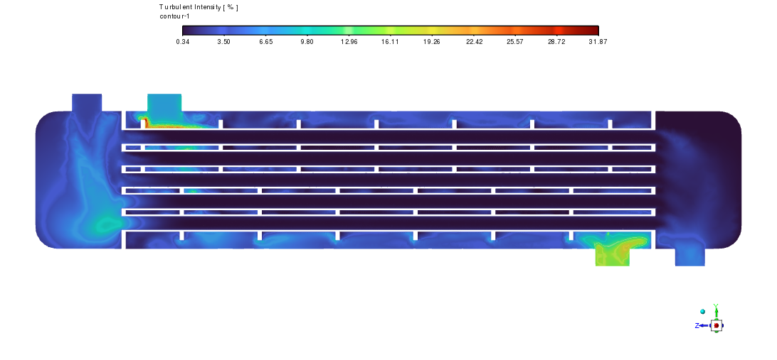
Figure 2: Temperature changes over a section plane in parallel flow arrangement
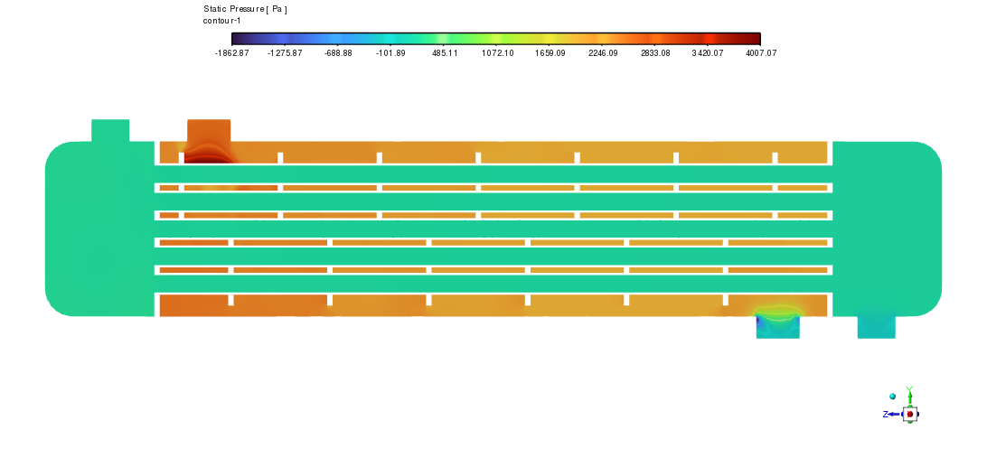
The longitudinal temperature distribution offers understanding of the thermal performance of the heat exchanger over its length. The slow temperature change as heat is transported between the fluids is shown by the red (hot) to blue (cool) color gradient. Both fluids enter from the same end and flow in the same direction, so clearly evident the parallel flow arrangement. The extreme contrast between red and blue areas at the entrance indicates that this arrangement produces a large initial temperature difference between the fluids; yet, the temperature difference reduces along the flow direction, therefore restricting the general heat transfer efficacy. The thermal patterns also imply that the most efficient heat transfer takes place in the center region of the heat exchanger; the efficacy declines near the outlet because of the declining temperature differential between the two fluids.
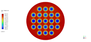
Figure 3: Conjugate heat transfer in copper bundle walls


Reviews
There are no reviews yet.