


A Phase Change Material (PCM) Melting In Tube With Fins CFD simulation is a computer model of a Latent Heat Storage system. PCMs are special materials that can store and release large amounts of energy when they melt and freeze. This Thermal Energy Storage Simulation is very important for making heat exchangers more efficient. Adding fins to the tubes creates a larger area for heat transfer. This helps the PCM melt faster. The main goal of this project is a PCM Melting in Tube CFD Validation. This means we compare our simulation results to the data from a trusted research paper, “Enhance heat transfer for PCM melting in a triplex tube with internal–external fins” [1], to prove our model is accurate.
- Reference [1]: Mat, Sohif, et al. “Enhance heat transfer for PCM melting in triplex tube with internal–external fins.” Energy conversion and management74 (2013): 223-236.
![PCM configuration in triplex tube with internal-external fins [1]](https://cfdland.com/wp-content/uploads/2024/10/PCM-configuration-in-triplex-tube-with-internal-external-fins-1.png)
Figure 1: The geometry configuration of the triplex tube with internal-external fins used for the Latent Heat Storage CFD study, from the reference paper [1].
Simulation Process: Fluent Setup, Solidification and Melting Model for Transient Thermal Analysis
To perform this Heat Exchanger CFD study, we first created the geometry in Design Modeler based on the reference paper [1]. The design includes a triplex tube made of copper with eight fins attached to the inner and middle tubes. Because the design is symmetrical, we could smartly model only half of it and use the axisymmetric option, which saves a lot of computer time. We used a technique called blocking to create a very high-quality structured grid with 20,608 hexahedral cells. In ANSYS Fluent, we activated the Solidification and Melting model to simulate the melting process. To ensure our PCM Melting in Tube Fluent Validation was accurate, it was critical to use the exact same material properties for the PCM and copper as reported in the paper [1].
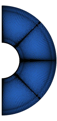
Figure 2: A professional visual of the structured hexahedral grid with 20,608 cells used for the PCM Melting in Tube Fluent Validation.
Post-processing: CFD Validation, Melting Rate and Heat Transfer Analysis
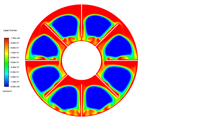
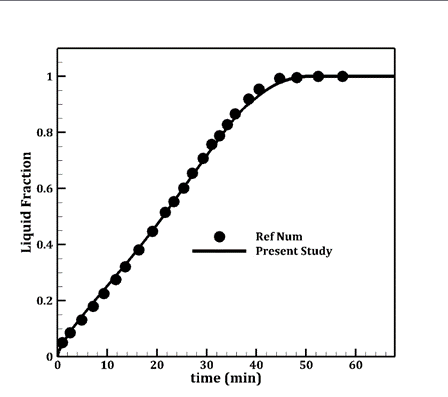
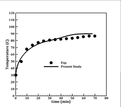
The validation graphs provide the most important professional visuals for this study, as they are the proof of accuracy. From an engineering standpoint, the liquid fraction graph (Figure 3b) shows an excellent agreement between our simulation results and the paper’s data. This match is critical because it confirms our model’s ability to correctly predict the rate of melting and the time it takes for the PCM to become fully liquid. The temperature graph (Figure 3a) also shows a very close match, which validates that our simulation is accurately calculating the conduction and convection heat transfer within the system.
Figure 3: Professional graphs from the CFD Benchmark Validation, comparing simulation results (our work) to experimental data [1] for a) temperature and b) liquid fraction over time.
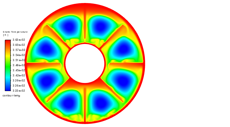
The temperature contour (Figure 4) provides a diagnostic map of the melting physics. The higher temperatures near the fins show that they are working as intended, acting as high-speed pathways for heat to travel deep into the PCM. This is important because PCMs often have low thermal conductivity. The shape of the melted region (the red and yellow area) is not perfectly circular; it is wider at the top. This is a sign of natural convection, where the warmer, lighter liquid PCM rises and moves heat around, a complex effect that our model successfully captures. The most important achievement of this simulation is the successful validation against trusted experimental data, which proves that our CFD model, including the Solidification and Melting settings, is a reliable and accurate engineering tool for designing and optimizing advanced thermal energy storage systems.
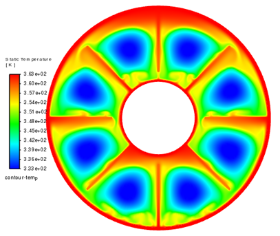
Figure 4: A professional temperature contour from the Transient Thermal Analysis, showing the melting process and the effect of the fins at a specific moment in time.


Reviews
There are no reviews yet.