


In many modern industries, such as HVAC and electronics cooling, space is very limited. Engineers need devices that can transfer a lot of heat without taking up much room. The Serpentine Heat Exchanger is a perfect solution. It uses a long, winding tube bent into a snake-like shape. This design packs a huge surface area into a small volume, allowing the fluid more time to heat up or cool down. But the real secret to its efficiency isn’t just the length; it is the curved shape that creates special flow patterns which mix the fluid.
This project is a Serpentine Heat Exchanger CFD simulation designed to visualize these hidden flow patterns. It is important to clarify that this is a CFD simulation, not a validation study. We use ANSYS Fluent to see how the fluid moves inside the bends and how the heat is transferred. For more learning resources on thermal systems, please visit our Heat exchangers tutorials. Our simulation setup is guided by the methods found in the research by Awais et al. [1].
- Reference [1]: Awais, M., et al. “Computational assessment of Nano-particulate (Al2O3/Water) utilization for enhancement of heat transfer with varying straight section lengths in a serpentine tube heat exchanger.” Thermal Science and Engineering Progress20 (2020): 100521.

Figure 1- Schematic of the Serpentine Heat Exchanger showing the winding path.
Simulation Process: Modeling the Serpentine Heat Exchanger Simulation
To start this Serpentine Heat Exchanger Fluent tutorial, we first created the 3D geometry using Design Modeler. We swept a circular cross-section along a winding path to create the tube. The next critical step was meshing. We generated a grid containing 115,404 tetrahedral cells. We paid special attention to the walls by adding a boundary layer mesh. This means the cells are very small and thin near the pipe surface to accurately capture the heat transfer from the wall to the water.
In the ANSYS Fluent setup, we turned on the Energy equation to solve for temperature changes. We defined the fluid as liquid water. The boundary conditions were set to simulate a heating process: cold water enters the inlet at 298 K (25°C), while the walls of the serpentine tube are kept at a constant hot temperature of 324 K (51°C). The goal of this Serpentine Heat Exchanger simulation is to predict the outlet temperature and understand the flow physics.
Figure 2: Tetrahedral mesh with boundary layers used for the simulation.
Post-Processing: Analysis of Dean Vortices and Heat Transfer
A real analysis of the simulation results, based on the provided contours and data, reveals the complex physics that make this design so effective. The velocity contour is the key to understanding the performance. It shows that the water velocity reaches a maximum of approximately 0.923 m/s. However, if you look closely at the red areas in the contour, you will see they are not in the center of the pipe. Instead, the fast-moving water is pushed toward the outer wall of every bend. This happens because of centrifugal force. Just like you feel pushed to the side when a car turns a corner, the water is pushed outward as it flows around the bend. This force creates a secondary flow pattern called Dean vortices. These are two counter-rotating swirls that act like a mixer inside the pipe.
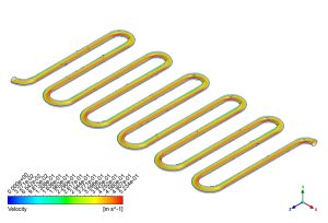
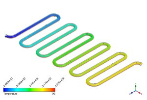
Figure 3: Velocity and temperature contours showing the mixing effect in the bends.
In a straight pipe, water flows in layers, and the layer touching the wall gets hot but doesn’t mix well with the cold center. This is called a thermal boundary layer, and it acts like a blanket, stopping heat transfer. The Dean vortices in this Serpentine Heat Exchanger CFD model destroy that blanket. They constantly scrape the hot water off the walls and push it into the cold center, while bringing cold water to the hot walls. The temperature contour proves this mixing is working perfectly. We see a smooth, continuous color change from blue at the inlet to orange at the outlet. The data shows that the water enters at 298 K and leaves at 318.13 K. This is a total temperature rise of 20.13 K. This impressive heating capability is directly caused by those Dean vortices mixing the fluid. The simulation confirms that the serpentine shape is not just about fitting a long pipe in a box; it is an active flow mixer that forces the heat to move efficiently.
Key Takeaways & FAQ
- Q: What are Dean vortices?
- A: Dean vortices are a pair of counter-rotating swirls created when fluid flows through a curved pipe. In this Serpentine Heat Exchanger CFD simulation, they are caused by centrifugal force and are essential for mixing the fluid and improving heat transfer.
- Q: Why does the velocity shift to the outer wall?
- A: As the fluid moves around the bend, centrifugal force pushes the heavier, faster-moving fluid to the outside curve. The contour shows this clearly with the high-velocity red zone (~0.923 m/s) located at the outer edge of the bends.
- Q: How efficient is the heat transfer in this model?
- A: The efficiency is high. The Serpentine Heat Exchanger ANSYS Fluent results show the water temperature increasing by 20.13 K (from 298 K to 318.13 K) as it travels through the winding path, proving the effectiveness of the design.


Reviews
There are no reviews yet.