

When it comes to high-speed aerodynamics, the interaction between supersonic flow and airfoils presents fascinating phenomena, particularly the formation and behavior of shock waves. When flow velocities exceed the speed of sound (Mach > 1), the NACA0012 airfoil, a symmetric airfoil widely used in aerospace applications, experiences distinct flow characteristics that significantly impact its aerodynamic performance. At Mach 1.5 and a 4-degree angle of attack (AOA), the supersonic flow around the NACA0012 airfoil generates complex shock wave patterns, including bow shocks, oblique shocks, and potential expansion waves. These shock waves, characterized by sudden discontinuities in flow properties such as pressure, temperature, and density, fundamentally alter the airfoil’s lift and drag characteristics. Understanding these supersonic flow phenomena and shock wave interactions is crucial for aerospace engineers in designing and optimizing aircraft components for high-speed flight conditions. As in 8th session of our ANSYS Fluent Course For Beginners, we delve into the compressible flow around a symmetric airfoil.
- Reference [1]: Doerffer, P. I. O. T. R., and O. S. K. A. R. Szulc. “Passive control of shock wave applied to helicopter rotor high-speed impulsive noise reduction.” TASK Quarterly. Scientific Bulletin of Academic Computer Centre in Gdansk3 (2010): 297-305.
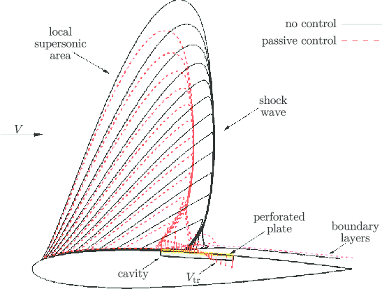
Figure 1: Classical passive control of shock wave on NACA0012 airfoil [1]
Simulation Process
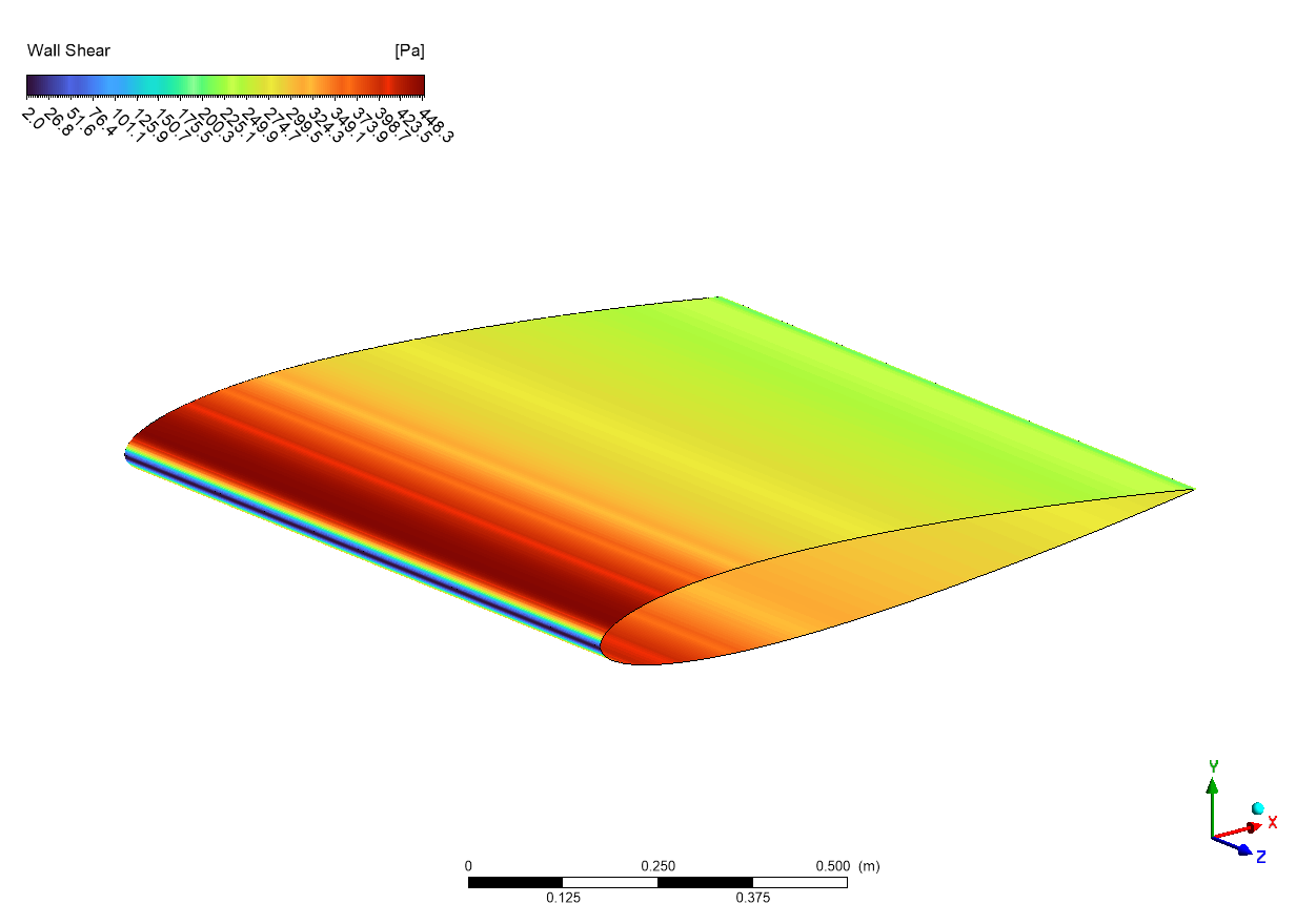
The numerical simulation was conducted on a three-dimensional NACA0012 airfoil model. Initially, the airfoil coordinates were obtained from a standard database and subsequently modified to conform to ANSYS Design Modeler specifications. To facilitate structured mesh generation, the computational domain was strategically divided into multiple blocks. The mesh topology was carefully designed to capture the complex flow features, particularly in regions where shock waves were anticipated. For turbulence modeling, the Spalart-Allmaras one-equation model was implemented, known for its robust performance in external aerodynamic applications. A pressure-based solver was employed, coupled with the ideal gas law to accurately account for compressibility effects at Mach 1.5. The temperature-dependent viscosity was modeled using Sutherland’s law. The simulation was performed at a freestream Mach number of 1.5 and an angle of attack of 4 degrees. The aerodynamic performance parameters, specifically lift and drag forces, were monitored.
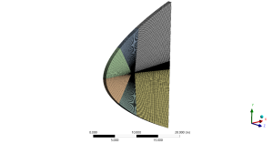
Figure 2: Structured grid over NACA0012 3D model
Results
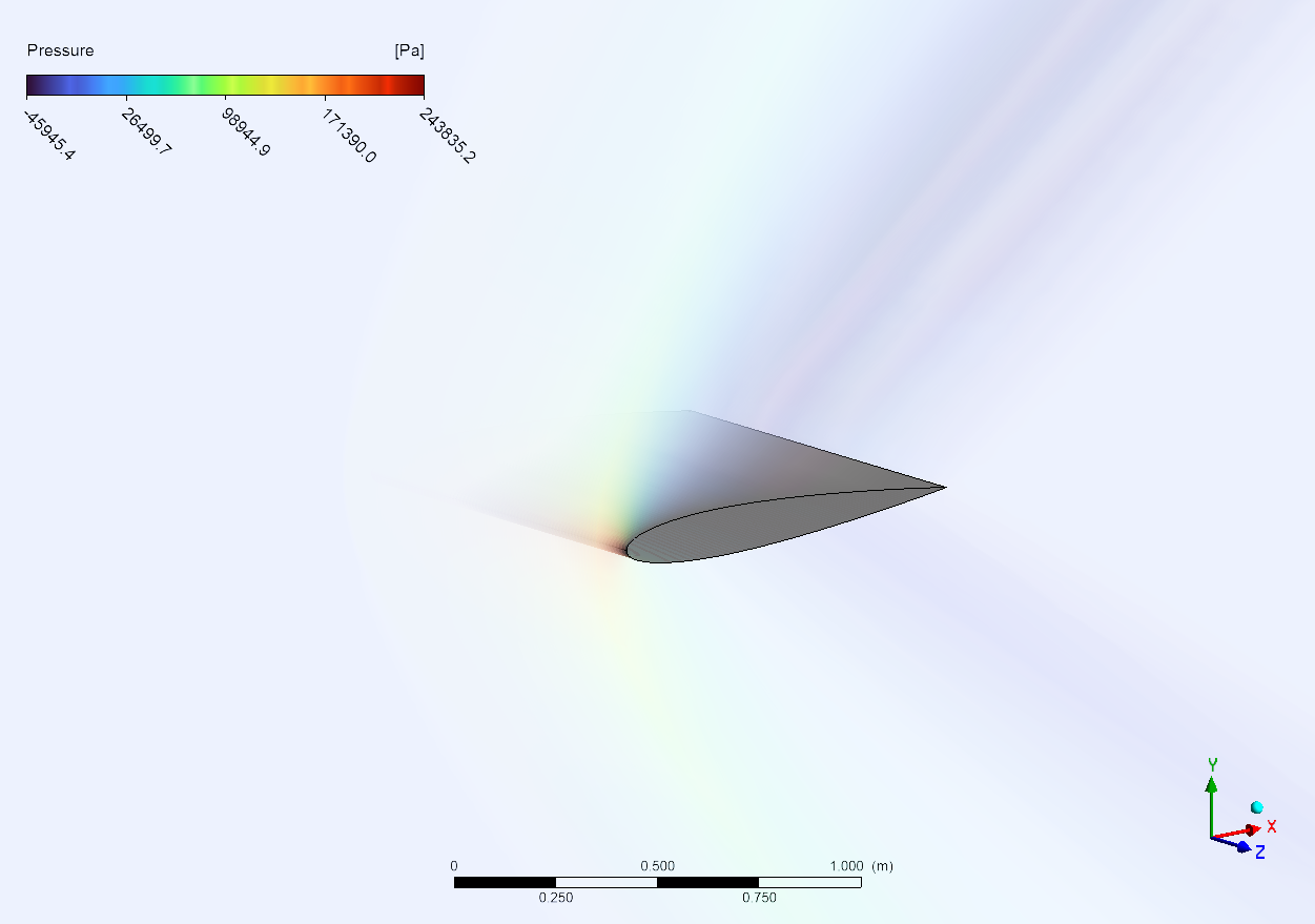
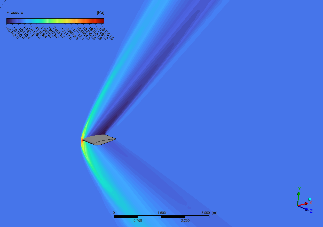
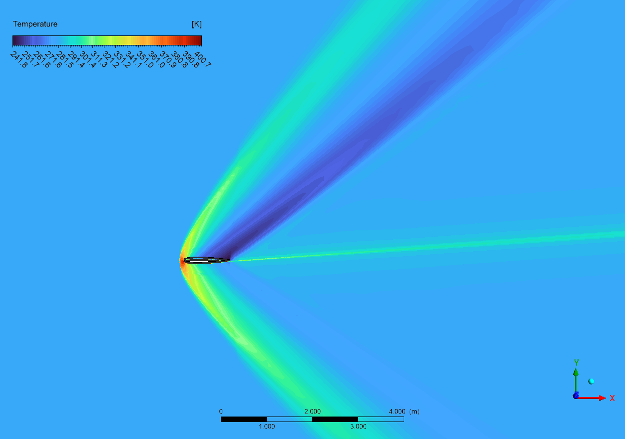
The pressure, density, and temperature contours reveal distinct shock wave patterns characteristic of supersonic flow at Mach 1.5 around the NACA0012 airfoil. A detached bow shock is observed ahead of the leading edge, indicated by the sharp discontinuity in all three flow properties. This detachment occurs due to the blunt nature of the airfoil’s leading edge and the supersonic freestream conditions. The 4-degree angle of attack creates an asymmetric shock pattern, with a stronger shock on the upper surface and a weaker shock on the lower surface, directly influencing the pressure distribution and consequently the lift generation.

Figure 3: Pressure distribution of supersonic flow around the airfoil CFD Simulation
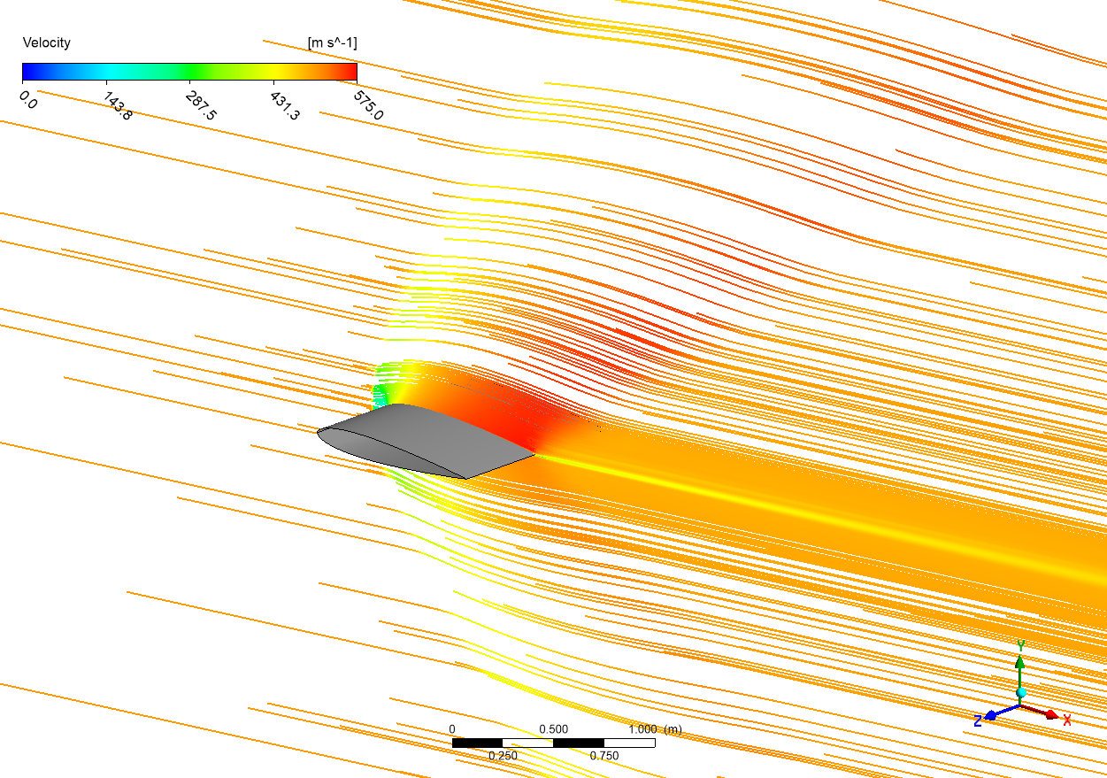
The flow field exhibits complex wave structures, including oblique shock waves and expansion fans. The pressure contour shows a high-pressure region (indicated by red/yellow) at the leading edge stagnation point, where the kinetic energy of the flow is converted to pressure energy. The density and temperature contours correlate well with the pressure distribution, following the compressible flow relations. Particularly noteworthy is the expansion region over the upper surface, characterized by lower pressure and density values (blue regions), which is consistent with the supersonic flow acceleration around the curved surface. The shock-induced boundary layer interaction is also evident, especially near the trailing edge, where the flow properties show significant gradients.
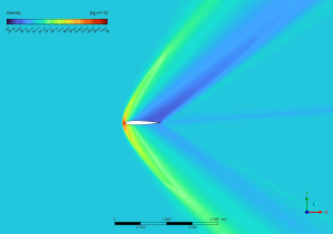

Figure 4: a) Density b) Temperature distribution of supersonic flow around the airfoil CFD Simulation


Reviews
There are no reviews yet.