


A Spiral Heat Exchanger is a highly efficient device known for its compact size and excellent thermal performance. Unlike standard exchangers, it uses two long metal sheets rolled into a spiral shape. This unique geometry creates two long, curved channels—one for the hot fluid and one for the cold fluid. This design provides a very large surface area for heat to move between the fluids, making it perfect for saving energy in tight spaces.
Engineers use Spiral Heat Exchanger CFD simulation to predict how well these devices will perform before building them. This project is a CFD simulation study designed to teach you how to analyze thermal efficiency. We will use ANSYS Fluent to model the flow, calculate the Log Mean Temperature Difference (LMTD), and determine the Heat Transfer Coefficient fluent output. For more in-depth learning on this topic, please visit our heat exchangers tutorials. Our methodology follows the principles outlined in the research by Bahiraei et al. [1].
- Reference [1]: Bahiraei, Mehdi, Hamid Kiani Salmi, and Mohammad Reza Safaei. “Effect of employing a new biological nanofluid containing functionalized graphene nanoplatelets on thermal and hydraulic characteristics of a spiral heat exchanger.” Energy conversion and management180 (2019): 72-82.
- Reference [2]: Zhang, Yanfeng, et al. “Numerical study on heat transfer enhancement in capsule-type plate heat exchangers.” Applied Thermal Engineering108 (2016): 1237-1242.
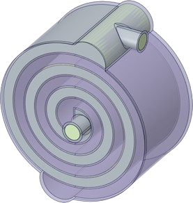
Figure 1: The 3D geometry of the spiral channels used for the CFD simulation.
Simulation Process: CFD Modeling of the Spiral Heat Exchanger
To start the Spiral Heat Exchanger fluent simulation, we first constructed the geometry. The model consists of three distinct domains: a fluid domain for the hot stream, a fluid domain for the cold stream, and a solid copper wall separating them. Copper was chosen because it conducts heat very well. After defining the parts, we generated a high-quality mesh. A precise mesh is essential for capturing the temperature gradients across the spiral walls. For this study, we created a mesh with approximately 1 million elements, ensuring the results are independent of the grid size.
In the ANSYS Fluent setup, we defined the specific boundary conditions for the thermal analysis. The hot fluid enters the spiral at a temperature of 350 K. The cold fluid enters its separate channel at 280 K. The goal of this Spiral Heat Exchanger simulation is to see how much heat moves from the hot fluid, through the copper wall, and into the cold fluid. We set the solver to calculate the energy equation and monitor the outlet temperatures to determine the overall efficiency.
Two important output parameters, including Delta(T-LMTD) and heat transfer coefficient, are calculated based on the given equations:
![\[ \Delta T_{LMTD} = \frac{\Delta T_2 - \Delta T_1}{\ln(\Delta T_2/\Delta T_1)} \]](https://cfdland.com/wp-content/ql-cache/quicklatex.com-909044d1ef15c726b680882a323ba3cf_l3.png "Rendered by QuickLaTeX.com")
![\[ \Delta T_1 = T_{h,i} - T_{c,o}[/latex] [latex]\Delta T_2 = T_{h,o} - T_{c,i} \]](https://cfdland.com/wp-content/ql-cache/quicklatex.com-60819475835fc6dd3328ce2fd1eaa935_l3.png "Rendered by QuickLaTeX.com")
![\[ h = \frac{q''}{T_{wall} - T_{inf}} \]](https://cfdland.com/wp-content/ql-cache/quicklatex.com-d84c944338041b1cfc09d67f412096ef_l3.png "Rendered by QuickLaTeX.com")
Post-processing: LMTD and Heat Transfer Coefficient Calculation
The results of the Spiral Heat Exchanger ANSYS fluent simulation provide a clear picture of thermal efficiency. By analyzing the temperature field, we can trace exactly how the heat is exchanged. The hot fluid enters at 350 K and, as it travels through the spiral, it loses heat to the copper wall, exiting at a cooler temperature of 333 K. Simultaneously, the cold fluid enters at 280 K and absorbs that heat, exiting at a warmer 296.5 K. These four temperature values are critical. We use them to calculate the Log Mean Temperature Difference (LMTD). The LMTD represents the average temperature driving force across the entire length of the exchanger. Based on our simulation data, the calculated LMTD is 53.42 K. This value tells us the average thermal potential available to drive the heat transfer process.
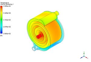
Figure 2: Temperature contours showing the heat transfer between the hot and cold spirals.
However, the most important metric for any thermal engineer is the Heat Transfer Coefficient. This number tells us how effectively the heat exchanger conducts energy per unit of area and temperature difference. Using the calculated heat flux and the LMTD, the simulation determined the heat transfer coefficient in heat exchanger to be 102.8 W/m²K. This specific value of 102.8 W/m²K is the key finding of this CFD analysis. It confirms that the spiral geometry, combined with the conductive copper wall, creates an environment where heat flows efficiently. The high surface area of the spiral design allows for this effective transfer even with a relatively small temperature difference. This study demonstrates the power of ANSYS Fluent in quantifying thermal performance and helping engineers optimize their designs for maximum energy saving.
Key Takeaways & FAQ
- Q: What is LMTD and why is it important?
- A: LMTD (Log Mean Temperature Difference) is the average temperature difference between the hot and cold fluids along the entire heat exchanger. In this Spiral Heat Exchanger CFD study, an LMTD of 53.42 K was calculated. It is important because it is the driving force that pushes heat from one fluid to the other.
- Q: How does the Heat Transfer Coefficient define performance?
- A: The Heat Transfer Coefficient measures how easily heat can pass through the wall and into the fluid. A higher number means better performance. Our result of 102.8 W/m²K indicates the specific efficiency of this copper spiral design in ANSYS Fluent.
- Q: Why use a Spiral Heat Exchanger over other types?
- A: Spiral Heat Exchangers are chosen for their self-cleaning effect and high surface area in a small footprint. As shown in this simulation, the spiral shape allows for a long flow path (good for heat transfer) without taking up much physical space in a factory.


Reviews
There are no reviews yet.