
Twin screw pumps are special machines that move liquids from one place to another. They work by using two screws that spin next to each other but don’t touch. These pumps are really good at moving thick, sticky fluids that other pumps can’t handle. Also, they can even move mixtures of liquids and gases at the same time! Many companies use twin screw pumps in oil fields, food factories, and chemical plants because they provide smooth flow without pulsing. When the screws turn, they create little pockets that trap the fluid and push it forward gently. This is why they’re called positive displacement pumps. One big advantage is that they keep pumping the same amount even when pressure changes. Plus, they don’t damage sensitive fluids like some other pumps do. However, it’s hard to see what happens inside these pumps during operation. That’s why we use CFD simulation to look at the flow patterns without cutting open real pumps. This helps engineers make better pumps that use less power and last longer. Moreover, good twin screw pump design must think about many things like how much fluid it can move, how high it can push pressure, and how to prevent parts from wearing out too quickly.
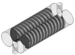
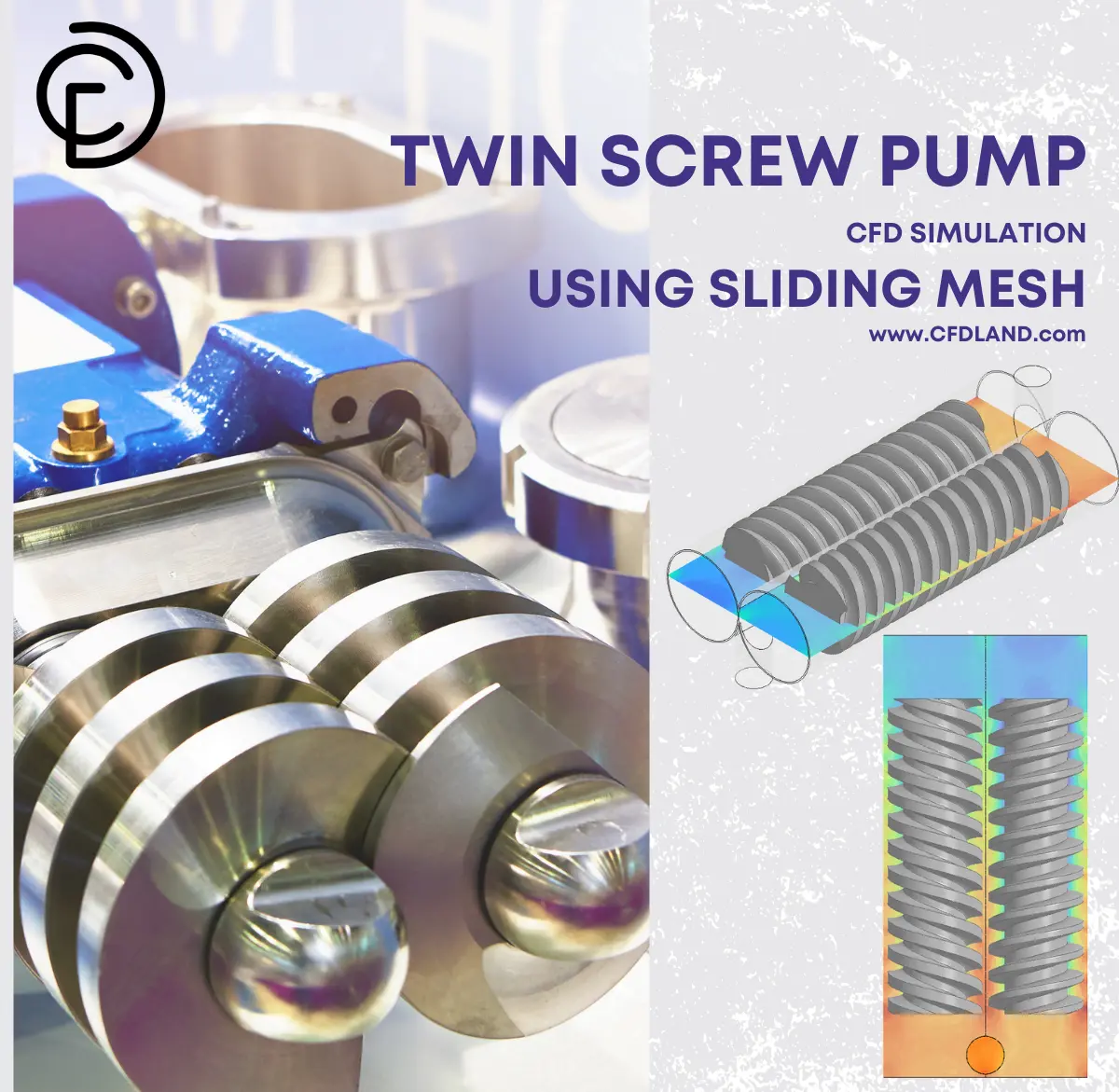
Figure 1: Twin screw pump model
Simulation process
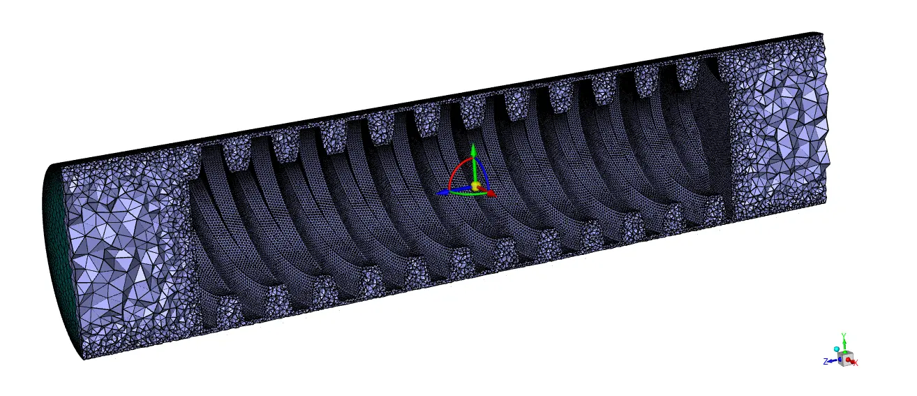
For this study, we set up a CFD model of a twin screw pump using ANSYS Fluent. First, we created an unstructured grid because it can better fit the complex shape of the screws. Using tetrahedral elements helps us capture all the curved surfaces and tight spaces between screws. Next, we applied the Sliding Mesh (Mesh motion) technique to handle the spinning motion of the screws. This means a simplification is considered. For a realistic approach, we need to employ dynamic mesh where the screws are closely rotating. In our setup, both screws rotate at 7.5 rad/s but in opposite directions, just like in a real pump. Furthermore, we set up the solver to run as a transient case with small time steps to capture the detailed flow patterns as the screws turn.
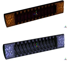
Figure 2: Generated grid over twin screw pumps using Fluent Meshing
Post-processing
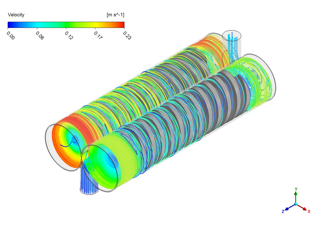
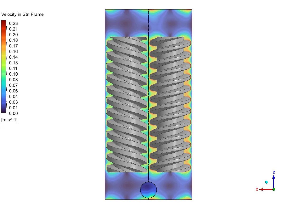
Looking at the velocity results, we can see how the fluid moves around the twin screws as they spin. The colors show different speeds, with blue being slow (around 0-0.03 m/s) and green-yellow being faster (about 0.11-0.17 m/s). What’s really interesting is how the fastest parts (yellow regions) form in the small gaps between the screws and the pump wall. This happens because the fluid gets squeezed through these tight spaces, just like when you put your thumb over a garden hose to make water shoot out faster. Also, the pattern repeats along each thread of the screws, creating a series of fast-moving zones that help push the fluid upward. The blue regions at the top and bottom show where fluid moves more slowly because there’s more space for it to spread out. Furthermore, this flow pattern shows how the twin screw pump creates a steady, even flow without the pulsing you’d get from other pump types.

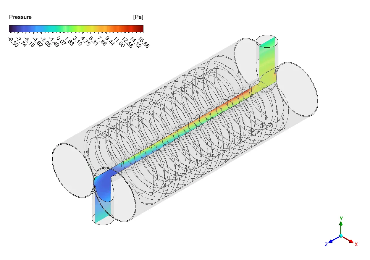
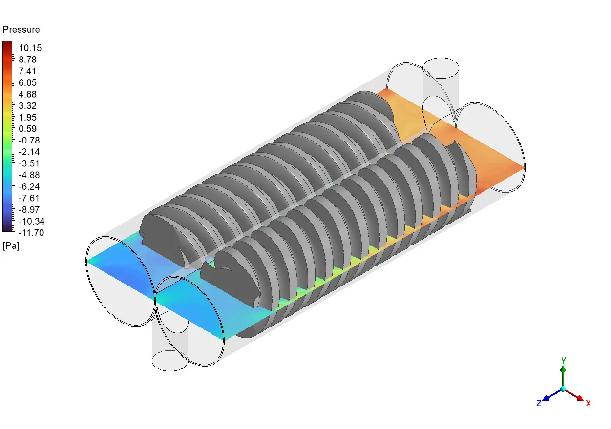
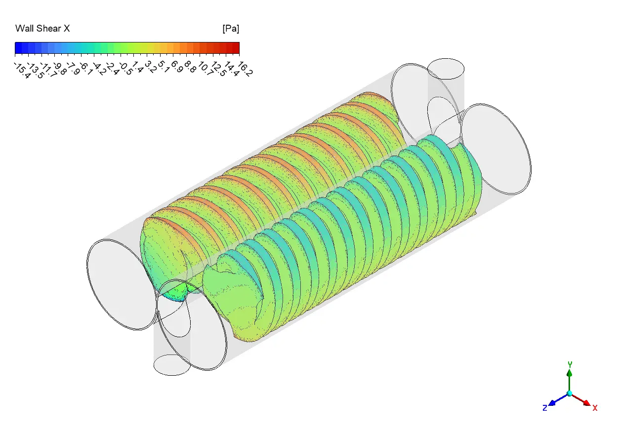
Figure 3: Pressure increase within the screws
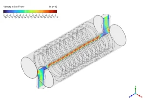
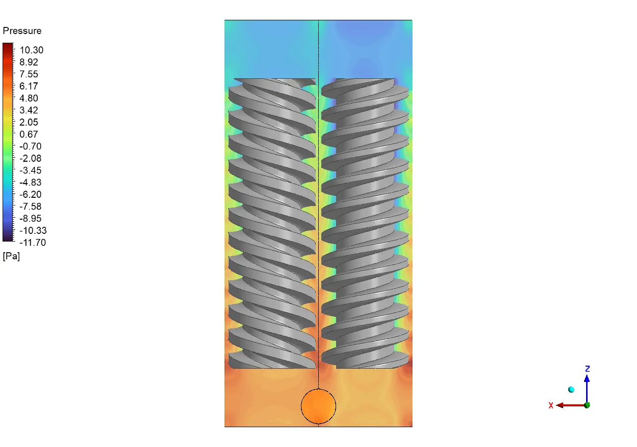
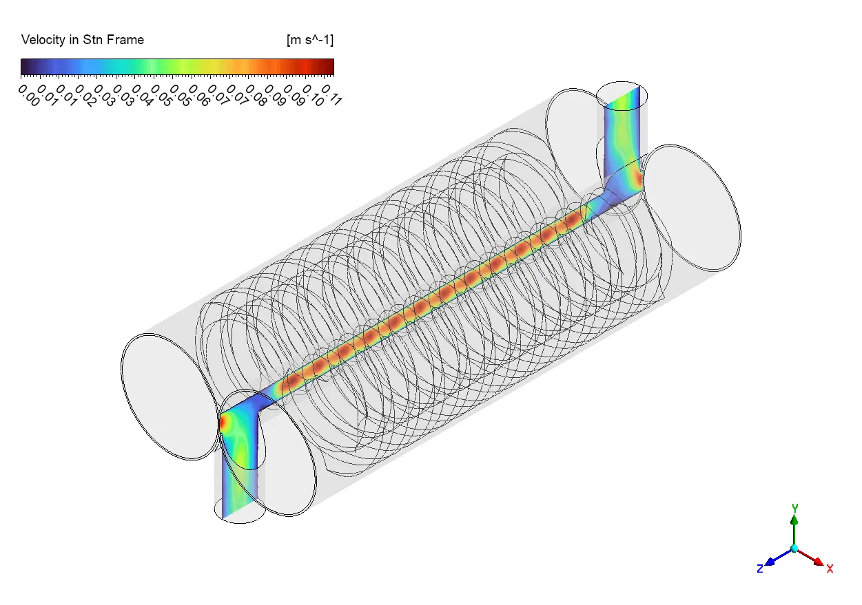
Figure 4: Velocity distribution in the midplane of screw pump
zhe pressure picture tells us even more about how the twin screw pump works. We can see a clear change in pressure from bottom to top, with orange-red colors at the bottom (high pressure, around 6-10 Pa) and blue colors at the top (low pressure, around -8 to -11 Pa). This pressure difference is exactly what drives the fluid upward through the pump. What’s clever about the screw design is how the pressure builds gradually through each screw rotation, which helps prevent damage to sensitive fluids. The yellowish-green areas between screw threads show the stepped pressure increase as fluid moves from one chamber to the next. This creates a smooth pressure gradient that’s important for pump efficiency. Plus, the pressure pattern on both screws matches almost perfectly, showing that they work together as a team to move fluid. The small clearances between screws create good sealing zones that help the pump achieve higher volumetric efficiency by preventing fluid from leaking backward.


Reviews
There are no reviews yet.