


The U-tube Shell and Tube Heat Exchanger is a cornerstone of industrial thermal management. Unlike straight-tube designs, this device features a bundle of tubes bent into a “U” shape. This unique geometry allows the tubes to expand and contract freely with temperature changes, solving the problem of thermal expansion. One fluid flows inside these tubes, while a second fluid circulates around them within a large cylindrical shell. This design is widely used in power generation, chemical processing, and HVAC systems because it packs a large heat transfer surface area into a compact volume.
Performing a U-tube Shell and Tube Heat Exchanger CFD simulation is the most effective way to understand the complex fluid dynamics that occur inside the shell and the bends. This project is a CFD simulation, not a validation study. We utilize ANSYS Fluent to visualize the flow patterns and predict the thermal efficiency of the system. For those interested in learning more about these devices, please visit our heat exchangers tutorials.
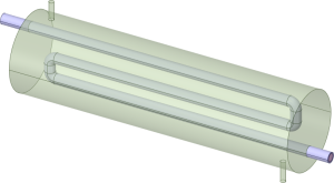
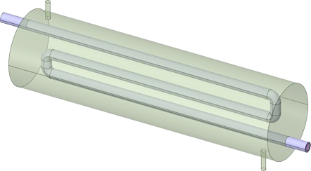
Figure 1: The 3D geometry design of the U-tube Shell and Tube Heat Exchanger.
Simulation Process: CHT Analysis in ANSYS Fluent
To start the U-tube Shell and Tube Heat Exchanger fluent simulation, we first developed a detailed 3D geometry. This model is divided into three distinct zones: the fluid domain inside the U-tubes (cold side), the fluid domain inside the shell (hot side), and the solid copper walls of the tubes themselves. Including the solid thickness is crucial because it allows us to perform a Conjugate Heat Transfer (CHT) analysis. This method calculates exactly how heat conducts through the solid metal from the hot fluid to the cold fluid.
After defining the domains, we generated a high-quality mesh consisting of 1,035,902 tetrahedral cells. A fine mesh like this is essential to capture the small-scale flow features, especially near the curved sections of the tubes. We then set up the physics for the U-tube Heat Exchanger CFD study. We defined the boundary conditions to match a typical industrial scenario: cold water enters the tubes at 290 K, while a hot fluid enters the shell side at 360 K. The simulation then solves the energy and momentum equations to determine how effectively the heat is transferred.
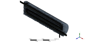
Figure 2: A cross-sectional view of the mesh created for the U-tube STHE CFD simulation.
Post-processing: How U-bend Vortices Drive Heat Transfer
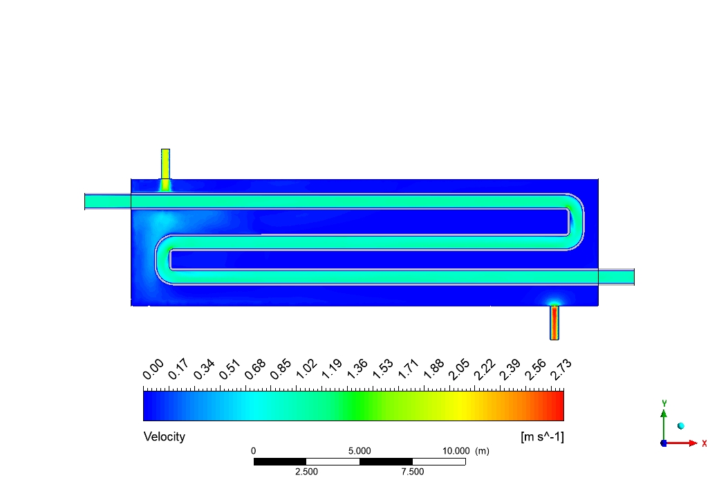
A deep analysis of the simulation results reveals the specific physical mechanisms that make the U-tube design so efficient. The velocity contour in Figure 4 highlights the flow dynamics, showing that the fluid reaches a maximum speed of 2.73 m/s, primarily near the narrow inlets and outlets. However, the most critical fluid dynamic phenomenon occurs within the curved U-bend section of the tubes. As the fluid is forced to turn 180 degrees, centrifugal forces act on it. These forces create a secondary flow pattern known as Dean Vortices. These are two counter-rotating vortices that swirl the fluid radially, moving it from the center of the pipe toward the outer walls. This swirling action is vital because it vigorously mixes the fluid. In a straight pipe, fluid layers can become stagnant, but the Dean vortices in the U-bend continuously disrupt the thermal boundary layer, forcing fresh, colder fluid from the core to come into contact with the hot copper walls.
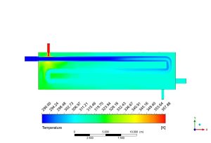
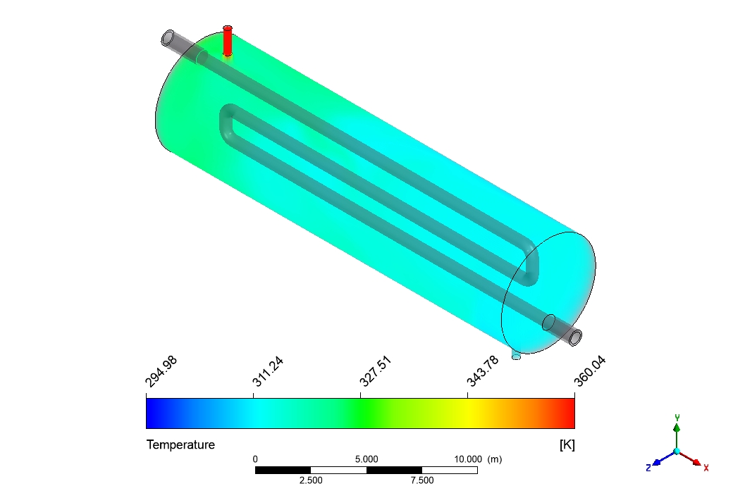
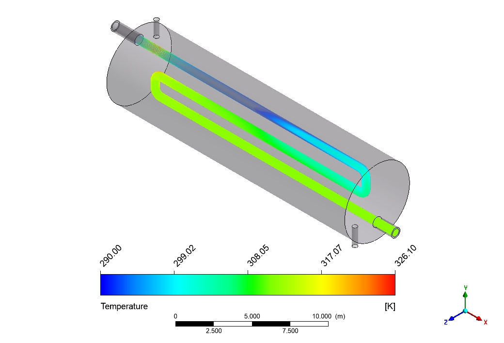
Figure 3: Temperature distribution in the U-tube Shell and Tube Heat Exchanger.
This enhanced mixing and boundary layer disruption directly lead to the impressive thermal performance observed in the temperature contours. The simulation data quantifies this heat exchange precisely. The cold water entering the U-tubes at 290 K absorbs a significant amount of energy, exiting the exchanger at 311.48 K. This represents a total temperature rise of 21.48 K. Conversely, the hot fluid on the shell side effectively releases its energy. It enters at 360 K and cools down drastically, leaving the system at 311.65 K, which is a massive temperature drop of 48.35 K. This substantial two-way energy transfer—heating the cold stream while cooling the hot stream—is the direct result of the optimized geometry and the secondary flows captured by this U-tube Shell and Tube Heat Exchanger ANSYS fluent analysis. The results prove that the turbulence generated by the U-bends plays a major role in maximizing the heat transfer coefficient.
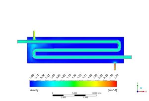
Figure 4: Velocity distribution, showing how the U-bend creates the flow patterns responsible for high performance.
Key Takeaways & FAQ
- Q: What are Dean Vortices in a U-tube heat exchanger?
- A: Dean Vortices are secondary, counter-rotating flow patterns that form in curved pipes (like the U-bend) due to centrifugal forces. As shown in this U-tube Shell and Tube Heat Exchanger CFD study, they improve heat transfer by mixing the fluid and breaking the thermal boundary layer.
- Q: What is Conjugate Heat Transfer (CHT)?
- A: Conjugate Heat Transfer (CHT) is a simulation technique that solves for heat transfer in both the fluid domains and the solid walls simultaneously. In this U-tube Heat Exchanger fluent simulation, it calculates the convection in the water/oil and the conduction through the copper tubes.
- Q: Why is the U-tube design preferred for high thermal differences?
- A: The U-tube design allows the tube bundle to expand and contract independently of the shell. This handles thermal expansion stress without damaging the device, making it ideal for applications with large temperature differences between the hot and cold fluids.


Reviews
There are no reviews yet.